Index:
UPDATED ✅ Do you want to use a potentiometer to measure the power of current from an Arduino? ⭐ ENTER HERE ⭐ and Learn Everything FROM ZERO!
If you have worked with Arduino surely you have already heard about what they are the potentiometersa very useful element on this platform that allows you to carry out different types of projectsas it is regulate the light intensity of an LED screen, control the position of a servo or in such case the speed of a motor. And it is that it has become one of the most common components used in this electronic platform.
Therefore, the potentiometers They are devices that will be used frequently to enter analog values on the Arduino board, so they can be used in a wide variety of electronic projects. It should be mentioned that they also have the ability to limit the flow of electrical current variably.
In this way, these devices allow modify the value of the current and the strain simply by varying what is the resistor value. In accordance with everything mentioned so far, here we are going to teach you a little more what are these components in Arduino and how can you start using themfor this, follow in detail everything that we are going to teach you next in the post.
What is a potentiometer and what are all the types that exist?

They are considered as a device that allows vary its resistance manually between what is a minimum value and a maximum value (Rmin – Rmax) in the case of the most common minimum values is the 0 ohmwhile in the maximum values the most common are 5k, 10k or 20k ohms.
These devices are internally made up of a moving contact that moves along a resistive track. In this way, when you move the potentiometer the contact moves along the track and it will vary the length of the section of track with which it is making contact, which causes resistance varies. potentiometers they usually have three terminalswhere two ends are linked to both track sides.
so both always record the maximum resistance Rmax. While the remaining terminal will correspond to mobile contact. In the case of this terminal, the resistance is varied with respect to the other two terminals as the potentiometer is actuated, thus being the sum of the resistance to the other terminals equal to the maximum resistance. It should also be mentioned that the potentiometers serve to limit what is the flow of electric current variably.
Causing a voltage drop in relation to resistivity. In the same way, it allows to modify the value of the current and voltage just by changing the value of the resistance. When it comes to control current and voltage levels within an electrical circuit, must be use the potentiometer. That is why it has an exclusive and characteristic use in those lighting projects in LED, LCD, among others.
It is also essential to mention that there are different types of potentiometers and which we are going to show you next in the post:
control potentiometers
This type of device is the most suitable to be used as an element of voltage control of electronic devices. To do this, the user must act on them in order to vary normal parameters of operation, such as the volume of a sound system.
In addition, there are different types of this control potentiometer, such as the following:
- Slide Potentiometers: In this case the resistive track is straight, so the cursor path will also be straight. They have been in fashion for a while now and are used mostly in graphic equalizers, since the position of their cursors represent the response of the equalizer. However, it should be mentioned that sliders are more fragile than rotary ones and take up more space and are also usually much more sensitive to dust.
- Rotary Potentiometers: They are controlled when their axis rotates, these are the most common, since they are long-lasting and take up much less space than the sliding ones. In addition, it should be mentioned that they are much more resistant.
- Multiple potentiometers: It is about several potentiometers with coaxial axes, in this way they end up occupying very little space. Instrumentation, car radios, among many others, are used for this.
adjustment potentiometers
They take care of check preset voltage, normally in factory. In this case users should not touch up, so it is not usually accessible from the outside. there are many encapsulated in plastic as many without capsulesand usually distinguish vertical adjustment potentiometers, where its axis of rotation is vertical and horizontal adjustment potentiometers with the axis of rotation parallel to the printed circuit.
According to the law of variation of the resistance, the following aspects are had:
- Logarithmic variation: The resistance will depend logarithmically on the angle of rotation, this is denoted with the letter A according to current regulations, since previously it was done with the letter B.
- Linear Variation: The resistance is directly proportional to the angle of rotation, currently it is denominated with the letter B, since before it was done with the letter A.
- Sinusoidal variation: In this case, the resistance is proportional to the sine of the angle of rotation, where two solidary sinusoidal potentiometers rotated at 90° can provide the sine and cosine of the angle of rotation.
- Anti logarithmic variation: Here the resistance is directly proportional to 10 with power the angle rotated, it is usually denoted by the letter F.
printed potentiometers
In this case the law of resistance is achieved by varying the width of the resistive trackwhile in the case of windings, the curve is adjusted to sections with wires of different thickness.
multiturn potentiometers
To carry out fine adjustments of the resistance there are multiturn potentiometersin this case the slider is attached to a screw des Multiplier, in such a way that to complete the route it needs several turns of the control organ.
digital potentiometers
It is thus called an integrated circuit where the operation simulates that of a analog potentiometer. It consists of a divider resistive of n+1 resistor with its n intermediate points connected to an analog multiplexer that selects the output. All of this is handled via a serial interface and usually has a tolerance in around 20% and to all this it is necessary to add the resistance due to the internal switches known as Rwiper.
In this case, the most common values are those of 10k and 100kalthough this may vary depending on the manufacturer with 32, 64, 128, 512 and 1024 positions in scale linear or logarithmic. This is handled by several manufacturers, but the main ones in them are Intersil, Maxim and Analog Devices. These devices have the same limitations as DAC converters, such as the maximum current that they can drain and that they are in the order of mA, INL and DNL.
What is a potentiometer for and why should you use it when working with Arduino?
potentiometers They are an electronic component very similar to the resistors, but this time with a resistance value that instead of being fixed is variable, thus allowing control the intensity of current through a circuit connecting it in parallel and the voltage drop connected in series. It can also be said that they are very similar to the rheostatbut the difference in this case is that the rheostat dissipate more power and is used for circuits with higher current.
According to this, potentiometers are mostly used to vary the voltage on a parallel circuit, while rheostats are used in series to vary the current. Therefore, it can be said that potentiometers are used for enter analog values on the Arduino board allowing to perform a complete action together with other components.
One of its functions can be the following:
- They allow to vary the speed of a motorregulate the intensity of light or vary the position of a servo motor.
In this way it can be said that potentiometers are devices that are used very frequently to modify variables desired either voltage or current. This is how it is very important to be able to know the resolution of the Arduino boardsince by having a resolution of 10 bit it means you have a maximum value of 1024. Taking all this into account, we will teach you how to use it on Arduino from scratch.
Learn step by step how to use a potentiometer with Arduino from scratch
Considering everything mentioned earlier in the post, here we are going to show you how to use potentiometer with arduino from scratchbearing in mind that this is a component that will be very useful when creating and programming projects from this platform.
To do this, follow each of the steps that we are going to teach you below:
Using the potentiometer with an Arduino board
In the case of working with Arduino UNO board you can count on 6 analog pins, they range from A0 to A5 and its most common use is the reading of data from analog devices such as the potentiometer. Here you get one 10 bit resolution which implies that you have 1024 values different, that is, it can read a range of voltages that go from 0V to 5V, detecting the possible voltage changes of 0.004V (5/1024).
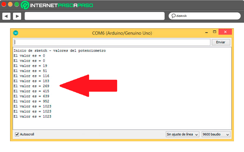
In this way, the values that will be obtained from go from 0 to 1023. So that you can understand all this better, here we are going to show you an example using the serial monitor where you can see what values are obtained in a analog pin according to how the position of the potentiometer is modified.
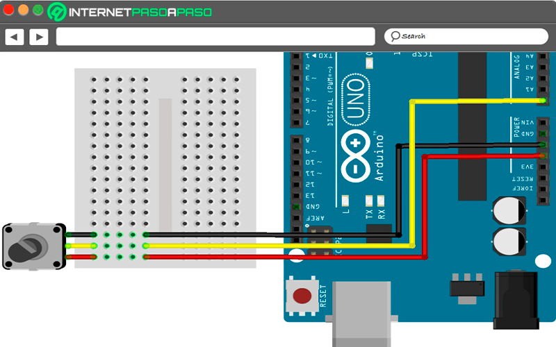
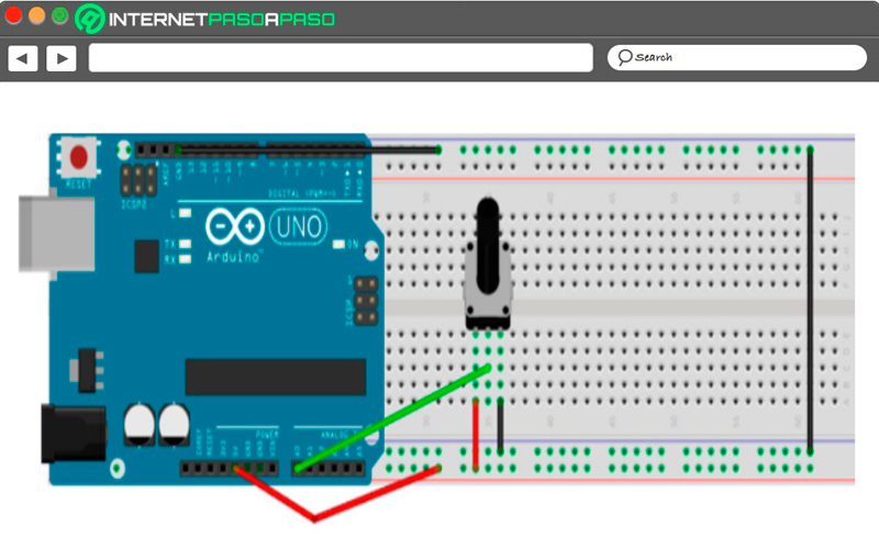
In the following image you can see the connection:

The code
Keep in mind that you must upload a code to the board, in this case you must upload the following code:
//Variable donde almacenaremos el valor del potenciómetro

Long valor;

Void Setup() {

//inicializamos la comunicación serial

Serial.begin(9600)


//Escribimos por el monitor serie mensajes de inicio

Serial.println("Inicio de sketch – valores del potenciómetro");

}

Void loop() {

//Leemos del pin Aø valor

Valor = analogRead(Aø)

//Imprimimos por el monitor serie

Serial.print("el valor es = ");

Serial.println(valor);

Delay(1000);
}
- When you’ve uploaded the code to the potentiometer on the board, the serial monitor should be opened. In this case the output will depend on the position of the potentiometer, As you turn the wheel you can see how the value changes.

- At one end the resistance will be minimal and will allow the 5 V value analog 1023 and at another end the resistance will be maximum and let go 0V analog value of 0.
So that you can understand all this in a better way, here we are going to show you another example of how to use the potentiometer on an Arduino board:
Turn on LEDs with a potentiometer on Arduino
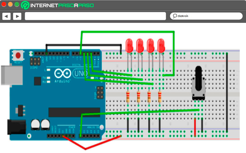
In this case 4 LEDs will be added to the circuitaccording to how the position of the potentiometer is modified, each one of the LEDs.
To do this, it will be necessary to assemble the circuit through the following scheme:

As seen, you can read 1024 different valuesthese range from 0 to 1023. Dividing this range by 4 and assign a range to each of the LEDs, you can control which LED is going to light depending on the input value on the analog pin.
The ranges of the values that have in these cases are the following:
- From 0 to 255LED 1 will light up.
- From 256 to 511 LED 2 will light up.
- From 512 to 767 LED 3 will light up.
- 768 to 1023 LED 4 will light up.
As the potentiometer is varying the analog input, it will be possible to turn on one LED and anotherthis will all be programmed using nested ifs.
Code
Here it will be necessary to use the variable resistor potentiometer property to turn on one and the other LEDthis will allow you to do a series of if to determine that LED will turn on and which one will turn off.
Depending on the values obtained at the analog pin input, the code would be as follows:
//Variable donde almacenamos el valor del potenciómetro

Long valor;


//Declaramos los pins de los LEDs

Int LED_1 = 2;

Int LED_2 = 3;

Int LED:3 = 4;

Int LED 4 = 5;


Void setup()  {

//Inicializamos la comunicación serial

Serial.begin(9600);


//Escribimos por el monitor serie mensajes de inicio

Serial.println("Inicio de sketch – valores del potenciómetro");

pinMode(LED_1, OUTPUT);

pinmode(LED_2, OUTPUT);

pinMode(LED_3, OUTPUT);

pinMode(LED_4, OUTPUT);

}


Void loop() {

//Leemos del pin A ø valor

Valor = analogRead(Aø);
}


//Imprimimos por el monitor serie

Serial.print("El valor es = ");

Serial.println(valor);


If(valor >= ø && valor <=225)

{

Digitalwrite(LED_1, HIGH);

DigitalWrite(LED_2, HIGH);

DigitalWrite(LED_3, HIGH);

DigitalWrite(LED_4, HIGH);

}
Computing