
Index:
UPDATED ✅ Do you want to assemble and program a robotic arm with Arduino? ⭐ ENTER HERE ⭐ and Learn Everything FROM ZERO!
If you want build a robotic arm with an Arduino board, then you will have to continue reading until the end. We will tell you, in detail, all the information you need to know to carry out this project without making mistakes.
The first thing we’ll show you are the components you need to create your first robotic arm. Then, we will explain the step by step that you must follow to create these projects with Arduino right from the start.
Finally, you will be able to read about the programming codes you will use and the best Arduino kits you can buy to practice the projects that we will indicate. Check out.
What do I need to build a robotic arm with Arduino from scratch?
To build a robotic arm with Arduino from scratch you will need to cover the aspects, the software and the hardware. Within the first group is the Arduino programming environmentcalled SDI.
Download Arduino IDE for Windows
Download Arduino IDE for MacOS
As for the hardware you will need:
- An Arduino model UNO board. This device has an ATmega328 microcontroller, with 6 analog inputs and 14 digital pins. It has one connector for power and one for a USB port. In addition, it has a button to reset the tasks.
- A generic robotic arm that you can make it with a 3D printer, or a device of a specific model, for example a Tinkerkit Braccio or a LittleArm MG995. In order for you to decide on one or another model, you must take into account the functions that you want the robot to perform, for this it will be necessary to have more or less servos.
- DC motors. Typically, a small robotic arm has between five and six servos. These motors execute their duty cycle using a 20 microsecond PWM. So you are going to need two types of servos, one; the SpringRC SR311 model for the rotation of the wrist and the gripper, and the second; the SpringRC SR431 to drive the robot’s body, shoulder and arm.
- A module for bluetooth technology HC-05. With this hardware you will be able to control the robotic arm wirelessly. The standardized IEEE 802.15.1 protocol is going to be used, so you will need to connect pins 1 and 2 to the USART serial port.
- A 5v joystick. This potentiometer will work between 0 and 5v and will take into account the voltage signals in a Vx and Vy plane.
- Generic cables and connectors.
Learn step by step how to build a robotic arm with Arduino from scratch
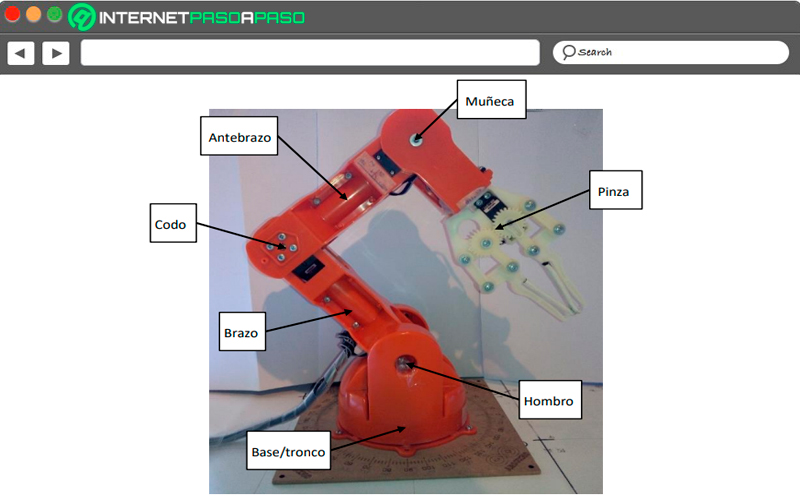
Next, we will show you how you should proceed to assemble your first robotic arm:
Recognizes all pins and sectors of the Arduino board
The first thing you should do is familiarize yourself with the Arduino board. For this it is important that you start reading the inspections that are recorded in the electronic circuits. You will notice that you will find a series of pins or inputs that are used in various jobs. In one corner you will find a (RESET) button that you can use to restart the board when it is malfunctioning or you want the whole process to restart. Inside that same side you will have the analog pins, the 5V and 3.3V input ones and the Vin.
On the shorter side, you will see the inputs for the external power supply and the USB. While for the other sector you will find the digital pins, the ground pin (GND), the tx output, the rx input, and an analog reference pin. Inside the board you will have the microcontroller, resistors, transistors and expanders. Once you have clear all the components of the Arduino UNO model you are ready to start with the assembly of the pieces.
Carry out bluetooth module connection
In this step you will have to connect the bluetooth module to the Arduino board. To do this you will have to choose the 5v pin of the HC-05 to the power input, the GND of the Arduino to the ground and the tx of the module to the rx of the Arduino. In turn, you are going to have to write the receive pin rx with the transmit pin of the Arduino (ie the tx or pin1).
Configure the HC-05 module
After having attached the bluetooth board to the Arduino, you will have to configure the module. To do this, you have to connect pin 34 of the HC-05 to a 3.3V source, then transmit voltage to it and, finally, place it in AT2 mode (you will realize this when the LED blinks slowly).
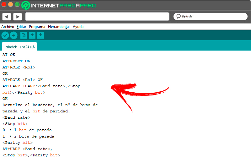
Enter the COM console and type the commands shown below in the following order:
AT.

AT+RESET.

AT+ROLE.

AT+ROLE=<Rol>. Siendo Rol 0 el esclavo y 1 maestro.

AT+UART. Con 0 un bit de parada y 1 dos bits de parada. Es del tipo <Parity bit>.

AT+UART=<Baud rate>, <Stop bit>, <Parity bit>.

AT+NAME. Para buscar el nombre del dispositivo cuando se encuentre conectado.

AT+ROLE=<Name>.

AT+PSWD.

AT+PSWD=<Password>. La contraseña tendrá que ser 4 dígitos.
Make the connection of the joystick to the Arduino board
What you should do now is attach the joystick to the Arduino board that will command the movements of the robotic arm. The connection is very simple, you just have to link both GND, connect the Vcc of the joystick to the 3.3V pin of the board and the VRx to the A0 pin of the Arduino. Finally, you are going to have to attach the VRy to A1 and the command SW to pin 4 on the board.
Attach the servos to the Arduino
What you will have to do now is connect the motors to the board using cables. For SpringRC SR311 model you will have to use the power to the 5V pin of the Arduino, the ground of the motor to the GND of the board and finally the amperage to pin 9. Regarding the servo SpringRC SR431you are going to connect the GND (brown and black) to the Arduino ground, the Vcc to each other and the SIG (white and orange) to pins 10 and 11, respectively.
Assemble the other pieces
This step will depend on the model of robotic arm you have. But so that you have a general idea, you must use all the screws to fix the remaining pieces with the acrylic plates and the plastics that you have. It is It is very important that you have the manufacturer’s manual for the robotic device at hand. so that you understand the correct union of the pieces.
Do the programming in the IDE
Once you have everything connected, you are now ready to program your robotic arm. But at this step we will see it in more detail below.
Discover how to program your robotic arm with Arduino so that it does what you want
To program the robotic arm that you just put together, you are going to have to go through this programming process:
Design a flowchart
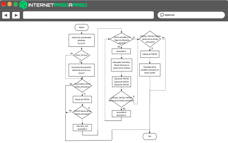
The first thing you will have to do is create all the actions and decisions You will need to take the programming codes into the development software. Considering the example of a robotic arm of the model Tinkerkit Braccio with 6 servos you will have to consider the following scheme: When you start the processthe program must calculate the coordinates, if there is a true error, correct it or go directly to the joint points to establish the limits.
In this step, you must perform the TETHA1 calculation to find out if it is within the joint limits. In case the mentioned limits do not correspond the process must be terminated. But yes elev=elev_min Y accessible=1, then the program must determine if it is an accessible point or if the maximum elevation is reached. If the answer is positive, it should be established whether TETHA2, TETHA3 and TETHA4 are within the limits of the joint.
If they are not, the process ends, but if they belong to the limit, then it will be the calculation of TETHAs to execute the saving of the joint variables and just finish the process. Secondly, if the accessible point does not reach the maximum elevation it must be established that the accessible=1 and produce the kinematic decoupling. This step to calculate the center of the wrist of the robotic arm, that is, the w-point. All of this will lead to the program having to calculate TETHA2, TETHA3 and TETHA4 to determine if they are within joint limits.
If not, then it will be given that accessible=0 Y elev=elev+n and it will be determined again if it is an accessible point or if it reaches a maximum elevation. If TETHA2, TETHA3 and TETHA4 are within the joint limits, it will be calculated and the joint variables will be saved within an auxiliary vector. So that graphically have this representation of the flow chartLook at the image we have prepared.
Login to IDE
Once you are clear about the processes that the robotic arm will carry out according to the flow chart, you will need to enter the Arduino programming environment, and which you downloaded from the main page. When you have executed the file, you will have to open the IDE and go to the tab File, Archivethen you will have to click on the option New to write the code that you will need to save later.
Configure the Arduino board
Make sure you have the UNO model configuredfor this you will have to go to the Tools function and then click on License plate. A menu will be displayed in which you will have to choose the version of the correct Arduino board.
Write the program commands
What you must do now is copy the codes that we show you below to execute the actions that the arm robotic Tinkerkit Braccio. You must consider that, if you choose another device model, the codes will be the same, but you will have to change the name of the libraries.
The steps are:
Get the robotic arm library for Arduino
In this case we take the Braccio hardware as an example, so we will show you the codes that you must enter in the Arduino IDE:
/ *

Comandos creados en este proyecto:

"/ arduino / custom / base / value: 80" -> Mueve la base del Brazo robótico a 80 grados

"/ arduino / custom / shoulder / value: 150" -> Mueve el hombro del Brazo robótico a 150 grados

"/ arduino / custom / elbow / value: 45" -> Mueve el codo del Brazo robótico a 45 grados

"/ arduino / custom / wristv / value: 10" -> Mueve la muñeca del Brazo robótico a 10 grados

"/ arduino / custom / wristr / value: 120" -> Mueve la muñeca del Brazo robótico a 120 grados

"/ arduino / custom / gripper / value: 73" -> Cerrar la pinza

"/ arduino / custom / ledon" -> Enciende el LED 13

"/ arduino / custom / ledoff" -> Apague el LED 13

"/ arduino / custom / servo: 3 / value: 73" -> Mueve el servo al pin 3 a 73 grados

"/ arduino / custom / sayAdios" -> Ejecute la función sayAdios (). Los Brazo robótico dicen "Adios" con la pinza

"/ arduino / custom / takesponge" -> Ejecuta la función takeponge (). El Brazo robótico lleva la esponja grande que puedes encontrar en su caja.

"/ arduino / custom / showsponge" -> Ejecuta la función showsponge (). El Brazo robótico muestra la esponja al usuario

"/ arduino / custom / throwsponge" -> Ejecuta la función throwsponge (). El Brazo robótico tira la esponja

/

# incluye < Wire.h >

# incluir < ArduinoWiFi.h >

# incluye < Servo.h >

# incluye < Braccio.h >

// Valor inicial para cada motor

int m1 = 0 ;

int m2 = 45 ;

int m3 = 180 ;

int m4 = 180 ;

int m5 = 90 ;

int m6 = 0 ;

booleano moveBraccio = falso ;

Base servo;

Hombro servo;

Codo servo;

Servo wrist_rot;

Servo wrist_ver;

Pinza servo;

configuración vacía () {

// Inicialización de Brazo robótico

comenzar ();

// Inicialización del Uno WiFi

comenzar ();

println ( "El servidor REST está activo " );

}

bucle vacío () {

// Espere hasta que la placa de Arduino reciba los comandos HTTP

mientras (Wifi. disponible ()) {

proceso (Wifi);

}

retraso ( 50 );

}

/ * *

Analiza un comando como: / arduino / custom / base / value: 45

Comando @param: el mensaje a analizar

@param type: la clave para analizar

@return el valor de la clave

/

int parseCommand (comando de cadena, tipo de cadena) {

int typeIndex = comando. indexOf (tipo);

int dotsIndex = comando. indexOf ( ' : ' , typeIndex + type. length ());

int idxtmp = dotsIndex + 4 ;

if ((dotsIndex + 4 )> comando. longitud ()) idxtmp = comando. longitud ();

String tmp = comando. subcadena (dotsIndex + 1 , idxtmp);

return tmp. toInt ();

}

/ * *

Procesa datos del protocolo HTTP

/

proceso nulo (cliente WifiData) {

// lee el comando

Comando de cadena = cliente. readString ();

toUpperCase ();

if (comando. indexOf ( " PERSONALIZADO " ) == - 1 ) {

println ( " Comando no válido: " + comando + " " );

volver ;

}

// El mensaje del remitente

Mensaje de cadena = comando. subcadena ( 16 );

// client.println (mensaje); //Depurar

/ *

Para cada mensaje, ejecute el comando adecuado

/

if (mensaje == " LEDON " ) {

// Enciende el Led 13

escritura digital ( 13 , ALTA);

// Devolver el mensaje al remitente (por ejemplo: el navegador)

println ( " alerta ('Led D13 ENCENDIDO'); " );

}

else if (mensaje == " LEDOFF " ) {

digitalWrite ( 13 , BAJO);

println ( " alerta ('Led D13 APAGADO'); " );

}

// Este comando le permite mover un servomotor deseado dando el

// Pin PWM donde está conectado

else if (mensaje. startsWith ( " SERVO " )) {

// Analizar el mensaje para recuperar cuál es el servo a mover

int servo = parseCommand (mensaje, " SERVO " );

// Analizar el mensaje para recuperar cuál es el valor del servo

int valor = parseCommand (mensaje, " VALOR " );

println ( " Mensaje: " + Cadena (mensaje) + " SERVO: " + Cadena (servo) + " " + Cadena (valor));

moveBraccio = verdadero ;

}

// Mando para la base del Brazo robótico (M1)

else if (mensaje. startsWith ( " BASE " )) {

m1 = parseCommand (mensaje, " VALOR " );

moveBraccio = verdadero ;

println ( " BASE: " + Cadena (m1));

}

// Mando para el hombro del Brazo robótico (M2)

else if (mensaje. startsWith ( " HOMBRO " )) {

m2 = parseCommand (mensaje, " VALOR " );

moveBraccio = verdadero ;

println ( " HOMBRO: " + Cadena (m2));

}

// Mando para el codo del Brazo robótico (M3)

else if (mensaje. startsWith ( " CODO " )) {

m3 = parseCommand (mensaje, " VALOR " );

moveBraccio = verdadero ;

println ( " CODO: " + Cadena (m3));

}

// Mando a la muñeca del Brazo robótico para moverlo hacia arriba y hacia abajo (M4)

else if (mensaje. startsWith ( " WRISTV " )) {

m4 = parseCommand (mensaje, " VALOR " );

moveBraccio = verdadero ;

println ( " WRISTV: " + Cadena (m4));

}

// Mando a la muñeca del Brazo robótico para rotarlo (M5)

else if (mensaje. startsWith ( " WRISTR " )) {

m5 = parseCommand (mensaje, " VALOR " );

moveBraccio = verdadero ;

println ( " WRISTR: " + Cadena (m5));

}

// Mando a la PINZA del Brazo robótico para abrirla y cerrarla (M6)

otra cosa si (mensaje. startsWith ( " PINZA " )) {

m6 = parseCommand (mensaje, " VALOR " );

moveBraccio = verdadero ;

println ( " PINZA : " + Cadena (m6));

}

// Comando para decir "Adiós"

else if (mensaje. startsWith ( " SAYADIOS " )) {

sayAdios ();

println ( " SAYADIOS: " + Cadena (m6));

}

// Comando para tomar la esponja

else if (mensaje. startsWith ( " TAKESPONGE " )) {

takeponge ();

println ( " TAKESPONGE: " + String (m6));

}

// Comando para mostrar la esponja o cualquier objeto

else if (mensaje. startsWith ( " SHOWSPONGE " )) {

showponge ();

println ( " SHOWSPONGE: " + Cadena (m6));

}

// Mando para tirar la esponja

else if (mensaje. startsWith ( " THROWSPONGE " )) {

lanzar esponja ();

println ( " THROWSPONGE: " + String (m6));

}

demás

println ( " error de comando: " + mensaje);

// si la bandera moveBraccio es verdadera, dispara el movimiento

if (moveBraccio) {

// cliente.println ("moveBraccio");

ServoMovimiento ( 20 , m1, m2, m3, m4, m5, m6);

moveBraccio = falso ;

}

flush ();

}

/ * *

El Brazo robótico Decir 'Adios' con el GRIPPER

/

void sayAdios () {

ServoMovimiento ( 20 , 90 ,   0 , 180 , 160 ,   0 ,   15 );

para ( int i = 0 ; i < 5 ; i ++) {

ServoMovimiento ( 10 , 90 ,   0 , 180 , 160 ,   0 ,   15 );

retraso ( 500 );

ServoMovimiento ( 10 , 90 ,   0 ,    180 ,    160 ,   0 ,    73 );

retraso ( 500 );

}

}

/ * *

Brazo robótico toma la esponja o cualquier objeto

/

void takeponge () {

// posición inicial

// (retardo de paso M1, M2, M3, M4, M5, M6);

ServoMovimiento ( 20 , 0 ,   45 , 180 , 180 ,   90 ,   0 );

// Muevo el brazo hacia la esponja

ServoMovimiento ( 20 , 0 ,   90 , 180 , 180 ,   90 ,    0 );

// el PINZA toma la esponja

ServoMovimiento ( 20 ,     0 ,   90 , 180 , 180 ,   90 ,   60 );

// sube la esponja

ServoMovimiento ( 20 , 0 ,    45 , 180 ,   45 ,   0 , 60 );

}

/ * *

Brazo robótico muestra el objeto al usuario

/

showponge vacío () {

para ( int i = 0 ; i < 2 ; i ++) {

// (retardo de paso M1, M2, M3, M4, M5, M6);

ServoMovimiento ( 10 , 0 ,    45 , 180 ,   45 ,   180 , 60 );

ServoMovimiento ( 10 , 0 ,    45 , 180 ,   45 ,   0 , 60 );

}

}

/ * *

Brazo robótico tira la esponja o cualquier objeto

/

void throwsponge () {

// (retardo de paso M1, M2, M3, M4, M5, M6);

ServoMovimiento ( 20 , 0 ,    45 , 90 ,   45 ,   90 , 60 );

ServoMovimiento ( 5 , 0 ,    45 , 135 ,   90 ,   90 , 60 );

ServoMovimiento ( 5 , 0 ,    90 , 150 ,   90 ,   90 , 0 );

}
Add more servos to your project
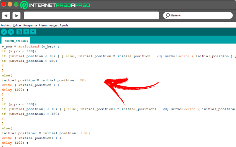
If you wish you can add more engines so that the robotic arm has more moves.
To do this you must enter the following codes in the program for each servo you add:
/*

Llamaremos servo1 al primer motor que puedes agregar

servo2 al segundo motor que añadas al brazo robótico

y así indefinidamente

*/

#include

Servo servo1;

Servo servo2;

int x_key = A1;

int y_key = A0;

int x_pos;

int y_pos;

int servo1_pin = 8;

int servo2_pin = 9;

int initial_position = 90;

int initial_position1 = 90;

void setup ( ) {

begin (9600) ;

attach (servo1_pin ) ;

attach (servo2_pin ) ;

write (initial_position);

write (initial_position1);

pinMode (x_key, INPUT) ;

pinMode (y_key, INPUT) ;

}

void loop ( ) {

x_pos = analogRead (x_key) ;

y_pos = analogRead (y_key) ;

if (x_pos < 300){

if (initial_position < 10) { } else{ initial_position = initial_position - 20; servo1.write ( initial_position ) ; delay (100) ; } } if (x_pos > 700){

if (initial_position > 180)

{

}

else{

initial_position = initial_position + 20;

write ( initial_position ) ;

delay (100) ;

}

}

if (y_pos < 300){

if (initial_position1 < 10) { } else{ initial_position1 = initial_position1 - 20; servo2.write ( initial_position1 ) ; delay (100) ; } } if (y_pos > 700){

if (initial_position1 > 180)

{

}

else{

initial_position1 = initial_position1 + 20;

write ( initial_position1 ) ;

delay (100) ;

}

}

}
Program the bluetooth module HC-05
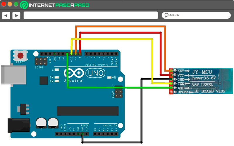
finish programming, you will need to include the actions to be performed by the electronic device so you have a functional joystick.
The instructions you will have to write are:
#include <SoftwareSerial.h>

SoftwareSerial BT1(10, 11); // RX | TX

void setup()

{ pinMode(8, OUTPUT); // Al poner en HIGH se fuerza el modo AT

pinMode(9, OUTPUT); // Este pin no es muy usado, por lo que podrás elegir otro

digitalWrite(9, HIGH);

delay (500) ; // Espera antes de encender el módulo

begin(9600);

println("Levantando el módulo HC-06");

digitalWrite (8, HIGH); // Enciende el modulo

println("Esperando comandos AT:");

begin(57600);

}

void loop()

{ if (BT1.available())

write(BT1.read());

if (Serial.available())

write(Serial.read());

}
List of the best Arduino kits to do robotics that you should know
You will find the best kits with materials to build your first robotic arm in Arduino:
Sunfounder 4-Axis Servo Control Robotic Arm – 180° Rotation
You can get this kit for around €70. It includes a clamp that can rotate up to 260° with a maximum opening of 9 centimeters, its arm being flexible thanks to the 4 DC motors it presents. Also included in this kit are 4 potentiometers for running interrupts, a USB cable for programming, and a kit of backbone. You must keep in mind that the Arduino UNO is not included in the kit, so you will have to buy it separately.
KeyEstudio Robotics Kit for Arduino
With this group of materials you will be able to assemble your first robotic arm in a very simple way. Includes an Arduino UNO R3 board, 1 x 2-module joystick, acrylic panels, 4 x 180° amplitude servos, cables, screws, and 1 Philip screwdriver. Its price ranges from €50 in the best electronic stores and includes a manual in Spanish.
Adeept 5-DOF Kit
The Arduino UNO board that comes with this kit will allow you to create an electronic arm to pick up things that they are not so heavy. It is ideal for beginners, since it includes a manual from 0 to 100 completely in Spanish. You will find in this kit a 2.5 centimeter OLED screen, 6 MG90S servos, acrylic caps, a bracket and a set of cables and screws. Its cost is around €105.
The best Arduino projects on robotics that you should know to practice
Look at the following projects that you can do with the knowledge you just acquired:
Robotic arm from Android
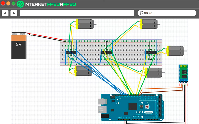
With this project you will be able to create an electronic device that allows you to move the robot by means of two motors. You will control it from your Android mobile via bluetooth. you’re going to need a plate Arduino Mega 2560, a robotic arm with movements at the elbow of 270°, at the wrist of 120° and at the base of 180°. You can choose, for example, the OWI 535 model.
You should also get a HC-05 bluetooth module, two DC type motors, leads for L293D motor, a 9v battery and a kit of cables for the connection. When you have everything ready, you will have to connect the left motor to pins 1 and 2, then you will have to connect the wheel of the right motor to inputs 4 and 5, next; you’re going to have to connect pin 6 and 7 to the hand servo and lastly; motor joint 2 and 3 with pins 8 – 9 and 10 – 11 respectively.
When you have these elements together you will have to assemble the joints 4 and 5 on pins 12, 13, 14 and 15. The tx of the board will be connected to the rx of the bluetooth module, while the tx of the HC-05 to the rx of the Arduino. Finally, you must connect the vcc port of the HC-05 to the 5v input of the board and the ground of both boards.
Once you have everything set up, you are going to have to go into the Arduino IDE and enter these programming sequences:
int inByte ;

configuración vacía ()

{

Serial . comenzar ( 9600 );

pinMode ( 2 , SALIDA );

pinMode ( 3 , SALIDA );

pinMode ( 4 , SALIDA );

pinMode ( 5 , SALIDA );

pinMode ( 6 , SALIDA );

pinMode ( 7 , SALIDA );

pinMode ( 8 , SALIDA );

pinMode ( 9 , SALIDA );

pinMode ( 10 , SALIDA );

pinMode ( 11 , SALIDA );

pinMode ( 12 , SALIDA );

pinMode ( 13 , SALIDA );

pinMode ( 14 , SALIDA );

pinMode ( 15 , SALIDA );

}

bucle vacío ()

{

si ( Serie . disponible ()  >  0 )

{

inByte =  Serie . leer ();

interruptor ( inByte )

{

caso '1' :

digitalWrite ( 2 , BAJO );

escritura digital ( 3 , ALTA );

digitalWrite ( 4 , BAJO );

escritura digital ( 5 , ALTA );

Serial . println ( "FRENTE" );

romper ;

caso '2' :

escritura digital ( 2 , ALTA );

digitalWrite ( 3 , BAJO );

escritura digital ( 4 , ALTA );

digitalWrite ( 5 , BAJO );

Serial . println ( "ATRÁS" );

romper ;

caso '3' :

digitalWrite ( 2 , BAJO );

digitalWrite ( 3 , BAJO );

digitalWrite ( 4 , BAJO );

escritura digital ( 5 , ALTA );

Serial . println ( "IZQUIERDA" );

romper ;

caso '4' :

digitalWrite ( 2 , BAJO );

escritura digital ( 3 , ALTA );

digitalWrite ( 4 , BAJO );

digitalWrite ( 5 , BAJO );

Serial . println ( "DERECHA" );

romper ;

caso '5' :

digitalWrite ( 2 , BAJO );

digitalWrite ( 3 , BAJO );

digitalWrite ( 4 , BAJO );

digitalWrite ( 5 , BAJO );

Serial . println ( "DETENER" );

romper ;

caso 'A' :

digitalWrite ( 6 , BAJO );

escritura digital ( 7 , ALTA );

Serial . println ( "RELOJ DE JUNTA 1" );

retraso ( 200 );

escritura digital( 6 , BAJO );

escritura digital ( 7 , BAJO );

romper ;

caso 'B' :

escritura digital ( 6 , ALTA  );

escritura digital ( 7, BAJO );

Serial .println ( "JUNTA 1 ANTICBLOQUEO" );

demora( 200 );

escritura digital ( 6, BAJO );

escritura digital ( 7, BAJO );

romper ;

caso 'C' :

digitalWrite ( 8 , BAJO );

escritura digital ( 9 , ALTA );

Serial . println ( "RELOJ DE JUNTA 2" );

retraso ( 200 );

digitalWrite ( 8 , BAJO );

digitalWrite ( 9 , BAJO );

romper ;

caso 'D' :

escritura digital ( 8 , ALTA );

digitalWrite ( 9 , BAJO );

Serial . println ( "JUNTA 2 ANTICBLOQUEO" );

retraso ( 200 );

digitalWrite ( 8 , BAJO );

digitalWrite ( 9 , BAJO );

romper ;

caso 'E' :

escritura digital ( 10 , BAJO );

escritura digital ( 11 , ALTA );

Serial . println ( "RELOJ DE JUNTA 3" );

retraso ( 200);

escritura digital ( 10 , BAJA);

escritura digital ( 11 , BAJA );

rotura;

caso 'F' :

escritura digital ( 10 , ALTA );

digitalWrite ( 11 , BAJO );

Serial . println ( "JUNTA 3 ANTICBLOQUEO" );

retraso ( 200 );

digitalWrite ( 10 , BAJO );

digitalWrite ( 11 , BAJO );

romper ;

caso 'G' :

digitalWrite ( 12 , BAJO );

escritura digital ( 13 , ALTA );

Serial . println ( "RELOJ COMÚN 4" );

retraso ( 200);

escritura digital ( 12 , BAJA);

escritura digital ( 13 , BAJA );

rotura;

caso 'H' :

escritura digital ( 12 , ALTA );

escritura digital ( 13 , BAJA );

Serial . println ( "JUNTA 4 ANTICBLOQUEO" );

retraso ( 200 );

digitalWrite ( 12 , BAJO );

digitalWrite ( 13 , BAJO );

romper ;

caso 'I' :

digitalWrite ( 14 , BAJO );

escritura digital ( 15 , ALTA );

Serial . println ( "RELOJ COMÚN 5" );

retraso ( 200 );

digitalWrite ( 14 , BAJO );

digitalWrite ( 15 , BAJO );

romper ;

caso 'J' :

escritura digital ( 14 , ALTA );

digitalWrite ( 15 , BAJO );

Serial . println ( "JUNTA 5 ANTICBLOQUEO" );

retraso ( 200 );

digitalWrite ( 14 , BAJO );

digitalWrite ( 15 , BAJO );

romper ;

}

}

}
Electronic device with four servos
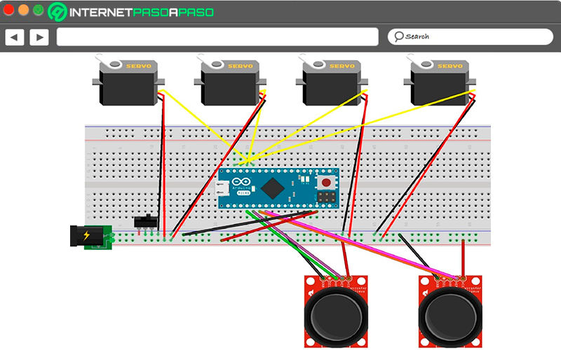
For this robotic arm you’re going to have to get a ArduinoMicro4 Tower Pro MG996R model servo motors, generic jumper cables and an analog joystick. When you make the connections taking into account the assembly image you will have to enter the programming environment.
Inside IDE write these actions:
#include <Servo.h>

Servo myservo1 ;

Servo myservo2 ;

Servo myservo3 ;

Servo myservo4 ;

Servo myservo5 ;

int potpin  =  0 ;

int potpin1  =  A1 ;

int potpin2  =  A2 ;

int potpin3  =  A3 ;

int potpin4  =  A4 ;

int val ;

int val1 ;

int val2 ;

int val3 ;

int val4 ;

configuración vacía () {

myservo1 . adjuntar ( 9 );

myservo2 . adjuntar ( 10 );

myservo3 . adjuntar ( 11 );

myservo4 . adjuntar ( 12 );

myservo5 . adjuntar ( 8 );

}

bucle vacío () {

val =  analogRead ( potpin );

val1 =  analogRead ( potpin1 );

val2 =  analogRead ( potpin2 );

val3 =  analogRead ( potpin3 );

val4 =  analogRead ( potpin4 );

val =  mapa ( val ,  0 ,  1023 ,  0 ,  60 );

val1 =  mapa ( val1 ,  0 ,  1023 ,  0 ,  100 );

val2 =  mapa ( val2 ,  0 ,  1023 ,  0 ,  100 );

val3 =  mapa ( val3 ,  0 ,  1023 ,  0 ,  100 );

val4 =  mapa ( val4 ,  0 ,  1023 ,  0 ,  100 );

myservo1 . escribir ( val );

myservo2 . escribir ( val1 );

myservo3 . escribir ( val2 );

myservo4 . escribir ( val3 );

myservo5 . escribir ( val4 );

retraso ( 25 );

}
robotic arm grip

This is a very simple example to carry out. It is an electronic arm built with a plate Arduino UNO that can pick up some objects with manual commands. It has four SG90 servo motors, a generic 9v battery, an on-on toggle switch, a generic breadboard, jumper wires, and a generic connector kit. The connection diagram will help you assemble all the components.
The programming codes that will make the robotic arm move are:
#include <Servo.h>

Servo motor1 ;

Servo motor2 ;

Servo motor3 ;

Servo motor4 ;

valor int ;

int grado ;

configuración vacía () {

attach ( 3 ) ;

attach ( 5 ) ;

attach ( 6 ) ;

attach ( 10 ) ;

}

bucle vacío () {

valor = analogRead ( A0 ) ;

grado = mapa ( valor, 0 , 1023,0,180 ) ;

write ( grado ) ;

valor = analogRead ( A1 ) ;

grado = mapa ( valor, 0 , 1023,80,150 ) ; // Con esta pieza, el valor del ángulo del servomotor debe ser diferente del estándar 0 -180 ya que la pinza podría tocar el suelo y desequilibrar el brazo. El ángulo limitado se define entre 80 -150°.

write ( grado ) ;

valor = analogRead ( A2 ) ;

grado = mapa ( valor, 0 , 1023,0,180 ) ;

write ( grado ) ;

valor = analogRead ( A4 ) ;

grado = mapa ( valor, 0 , 1023,0,180 ) ;

write ( grado ) ;

}
Computing