
Index:
UPDATED ✅ Do you want to know the secrets of Arduino programming and how to learn it? ⭐ ENTER HERE ⭐ and Discover Everything From Scratch!
The arduino boards are versatile electronic devices highly chosen by users. This is due to its low cost and all the features it offers. One of the most outstanding advantages it has is the ease provided by its programming environment.
For this reason, if you want to carry out any project, the Arduino-IDE it will not be an inconvenience for you, even if you have little computer knowledge.
But this does not mean that you should not know all the secrets that Arduino programming has. You will find this information below, so we invite you to continue reading.
What is Arduino programming and what are the most important fundamentals of it?
The first thing you should know is that Arduino is a small board with integrated digital circuits that are used to build a wide variety of devices. To do this, it is necessary to program this panel by means of codes that is done within an environment called IDE. In this cross-platform app development, the IDE, the lines of programming code are dumped to automate the tasks that Arduino will perform.
This is possible thanks to the reading carried out by the sensors to transmit the development in the actuators of the digital project. A clear example of this would be the building a traffic light with Arduino. To do this, it is necessary (explained in a general way) to write the codes, connect the different LEDs to the digital and analog pins, enter electrical current and wait for the plate to act with the environment.
The IDE is a simple piece of software that needs some tools to compile the program and remove it from memory. software that is no longer used from the processor. One of these tools is the sketch, which is assigned one for each project that you want to generate (hence, the sketch is often called a project). It is important to keep in mind that the folder that will contain the sketch must belong to a directory that must have the same name as the projectotherwise the file will not be recognized.
The structure of a project should always start the same way:
void setup() {

// en esta parte hay que empezar a escribir el código para que se ejecute

}

void loop() {

// permite que se ejecute el código en forma de bucle

}
In this way it is possible enclose blocks of code and have them loop continuously to maintain program statements and statements. It is important to clarify that setup() It will always be the function in charge of collecting all the data for the configuration and loop() allows the program to be constantly repeated so that the project makes sense.
All of the above can be saved in a library so that this set of functions can be well defined by the programmer and can be used without the need to establish each of the code steps again.
Secondly, the IDE allows in the programming to introduce comments to establish a function declaration or to introduce the library or the program. For this, it is necessary to establish some rules that allow short or long comments not to be considered by Arduino. all that is found between /* and */ is not taken into account by the programming environment.
For example:
/*

Internet Paso a Paso Curso de Arduino

*

Este es un programa básico de un semáforo para comprender los diferentes comandos y argumentos de una placa de Arduino. Encender un led rojo por segundo, luego un led amarillo mientras se apaga el rojo

después se apaga para encender el verde y así sucesivamente... Se usará el pin 13,

aunque esto dependerá del modelo de la placa de Arduino que tengas y de los elementos que quieras añadir

también se incluirá una resistencia, en caso de ser necesario.

*

más información https://internetpasoapaso.com/cursos-online-gratis/informatica/arduino/

*/
It is also possible to make comments on the same line including at the beginning //. This allows the program to avoid taking these parameters into account, but helps developers understand the reason for entering that code.
An example of this is:
int ledPin = 13; // conectamos el LED al pin 13, pero debes tener en cuenta el modelo de tu placa de Arduino
Variables are factors that you should also take into account. to save time on programming. It is a space that is used to store a data which must contain a name, a type and a value. If we follow the example of the semaphore, it has been used as a variable int ledPin = 13. Where int is the type of variable, ledPin your name and 13 the value assigned to a pin on the board. This allows you to quickly change the sketch if the pin assignment changes.
The set of variables that can be found in a schedule is, among others:
- Constants: true, integer, high and low.
- Type of data: array and bool byte.
- Scope and qualifiers: const, scope and volatile
- Conversion: float, long, word, string and byte.
- Others: PROGMEM size of, unsigned char and unsigned long.
Finally, the functions remainwhich are the procedures to be included in the code so that the board, through its sensors, performs a certain action.
There are a large number of functions which can be divided into:
- Digital input and output
- Analog input and output
- Math
- random numbers
- bits and bytes
- Special for Zero, Due and MKR plates
- Trigonometry
- external interrupts
- characters
- Advanced log in and out
- interruptions
- Weather
- Communication
- USB
An example of using the functions is:
/* todo lo ingresado entre { } se llama cuerpo de la función

*sirve para conocer todo lo que hace la función

*/

void setup()

{

pinMode(ledPin, OUTPUT); // con este código se llama a la función pinMode por

// medio de dos parámetros ledPin y OUTPUT

//pinMode funciona como una función de entrada y salida

}
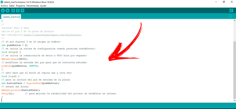
A tutorial that you can practice to turn on the LED that is on your plate is the following:
/*

Internet Paso a Paso

Led en el pin 2 de la placa de Arduino

más información https://internetpasoapaso.com/cursos-online-gratis/informatica/arduino/

*/

// el pin digital 2 se le asigna un nombre:

int pushButton = 2;

// se inicia la rutina de configuración cuando presiona restablecer:

void setup() {

// se inicia la comunicación en serie a 9600 bits por segundo:

begin(9600);

// modificar la entrada del pin para que se convierta entrada:

pinMode(pushButton, INPUT);

}

// esto hace que el bucle se repita una y otra vez:

void loop() {

// para la lectura del pin de entrada de la placa:

int buttonState = digitalRead(pushButton);

// estado del botón:

println(buttonState);

delay(1); // para mejorar la estabilidad del proceso se establece un retraso

}
Types of programming in Arduino What are all the ones that exist so far?
There are currently two ways of programming that you can use in Arduino. One of them is physical computing or physical computer development which consists of coordinating the actions of software and hardware to interact with people. It is done by means of the keyboard and the mouse, among other elements. This method It is useful for those projects that are carried out in a simple way. and that does not require great technical advances.
In general, it is a question of using the sensors and microcontrollers of the Arduino board by connecting electromechanical devices to analog kids. In this way it is possible to control lighting, servos and motors. While the second type of programming is called real-time or reactive computing. It is a way to configure an Arduino board to respond in a certain time through receiving data and from the environment.
This type of programming requires more computer knowledge because the responses of the microcontroller must be given in thousandths of a second. At the same time, the codes have to include loops that work correctly to restart the entire process, avoiding errors in programming and operation.
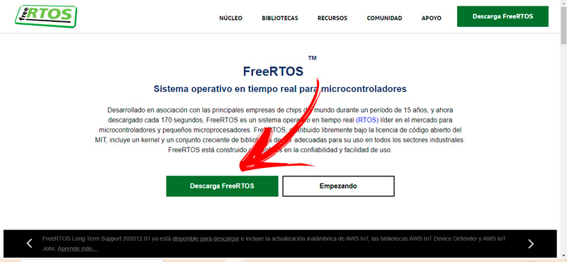
There are different operating systems that use real-time programming, distinguishing itself in this way from the rest of the OS that can take up to minutes to respond to user instructions. An example of this is FreeRTOSwhich is a real-time operating system for microcontrollers that you can’t download from their website https://www.freertos.org/.
Basic requirements to program in Arduino What should I know before starting in this world?
If you want to become an expert in Arduino programming It will be necessary for you to know some basic concepts that will help you in this world.
Therefore, take a look at the following list that will guide you in this stage:
- The first thing you should know is what an Arduino board is and how it is made up. This electronic component is a board that contains integrated circuits and different connectors that help to relate to the external environment. There are analog and digital pins, power input, ground connection, voltage regulator and clock, among other elements.
- Once you know what an Arduino board is, you must know its model.. Many people believe that all Arduinos are the same, which is incorrect because there are different versions that are better suited to each user’s need due to the functions and features it offers. It is important then that you know what model of plate you have in your hands.
- The above will help you to know precisely where all the inputs and outputs of the board are located. This will allow you to better know the voltage range with which it works, the number of digital and analog pins, the microprocessor and other functions. When you know these details you will know what kind of projects you can carry out.
- When you already know the hardware, it is the turn of the software. The Arduino programming environment is the Integrated Development Environment or IDE. It is a free and open source program that can work on both Windows, MacOS and Linux, making it a versatile tool. It is compatible with the C and C++ programming languages.
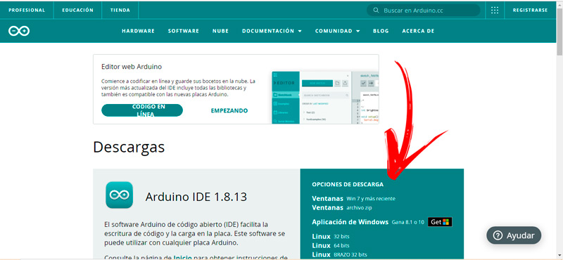
- Next, you will need to download the IDE for free. To do this you will need a computer with any of the operating systems that we mentioned before and then enter the page with your browser.
https://www.arduino.cc/en/software. This will allow you to choose the OS you have installed and continue with the steps in an easy way. - Once you have installed the program you will have to go to the desktop and click on the shortcut created by the software. This will open a new sketch which will include the first 2 mandatory programming commands, setup() Y loop().
- Know the programming structure. In this step you must understand what the programming structure is, what is a project, a function, a variable and an argument. You will find this information in the previous paragraphs of this post. Go to them and you will find everything you need.
Arduino Programming Manual Where can I download this guide for beginner programmers?
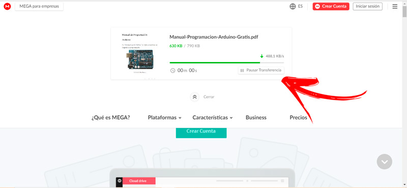
There are different sites where you can download an Arduino programming manual for beginners, but you have to keep in mind that some are not as easy as they say, others contain broken codes and others you have to spend too much money. For this reason we recommend that you download a complete computer development guide with Arduino in a safe and virus-free way.
You will be able to download the Arduino programming manual from your link here. This is a project that shows the structure, variables and data types that you can use in programming. In addition, you will find a complete guide on the communication between Arduino and the other programming systems and how to send on demand and convert an analog port to digital.
Learn step by step how the different ways of programming Arduino from scratch work
We will show you below the step by step that you must socialize in the different ways of programming Arduino from scratch:
Programming with Android
It is possible to use your smartphone or tablet with Android operating system to program an Arduino board, see below the procedure to perform:
- The first thing you will have to do is download the application ArduinoDroid – Arduino/ESP8266/ESP32 IDE from the Google store, Play Store.
- Next, connect an OTG or USB cable to the Arduino, this will depend on the model of the board. If the Arduino version is ADK, much better because this model is prepared to be compatible with Android.
- Link the board with your computer via USB.
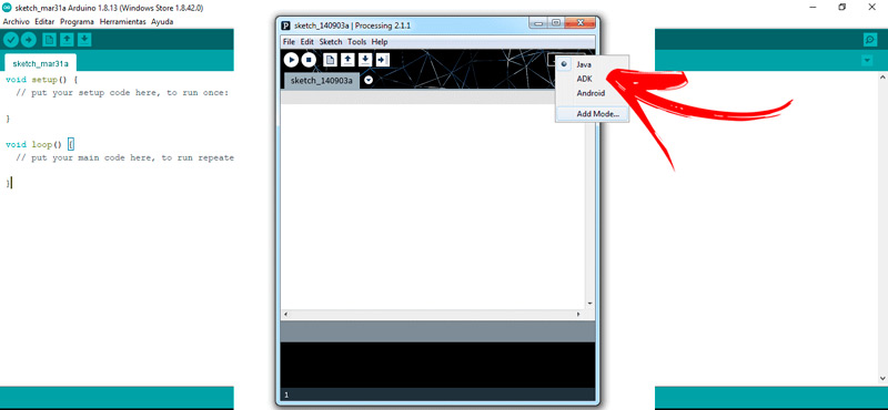
- Go to the top corner of the screen and tap on the 3 points. This will display the options menu.
- Click on the last tool, add mode.
- This will allow a new menu to open in which you will need to enter the ADK search bar. When you finish press on Search.
- Once you find the option, click on it and click on Install. At this step you can also do it by downloading the file
http://processing.arduino.cc/AdkMode.zip.
When you have finished with the previous steps, you must download the Arduino libraries by following this guide:
- low in
http://processing.arduino.cc/UsbHost.zipthe file UsbHost.zip. - Once you have unzipped the file you will find the folder USB ADK. Select it and move it to Arduino Sketchbook.
- turn off and on again the Arduino board.
Now install the Android SDK:
- Sign in to
http://developer.android.com/sdk/index.htmland press the button DOWNLOAD ANDROID STUDIO. - Follow the steps which the installation wizard will ask you.
- Opens SDKManager, you will find a list with all the available tools. Choose Android 3.1.
- Accept the terms of use and platform security policies.
Enable your device as a developer. For this you must follow this step by step:
- enter to the menu of your Android.
- Choose Settings.
- Click on the function About of the phone.
- press repeatedly (in some models it is 6 and in others the number is 8) in the option build number. This will allow the developer option to be enabled.
- Go back and press developer options.
- Activate the function ADB debugging via USB.
Install the drivers on your phone and perform an analog reading test with this guide:
- Opens processing and choose the ADK mode in the left corner.
- Go to the menu and select the tool File, Archive.
- look for the function examples and select it.
- Click on Basic concepts and then choose the tool AnalogRead.
- Choose Run on the device and wait a few minutes.
- You will see a code which you must copy it into the Arduino IDE. This will allow you to connect the Arduino with the mobile device and make them compatible.
- After a few seconds press on Carry.
- Press Behind to close the app.
- Disconnect the USB cable from the computer and plug it into the Arduino.
- If you did all the steps correctly you will find a sign on the screen of your phone wondering if you really want to connect an Arduino board, so you should click on Okay.
Try these example codes to see if you got the process right:
#include <LiquidCrystal.h>

#include <Servo.h>

#include <Wire.h>

#include <RFID.h>

#include <SPI.h>

Servo doorservo;

LiquidCrystal lcd(12, 11, 5, 4, 3, 2);

int inputPin = 6;

int pirState = LOW;

int val = 0;

#define SS_PIN 9

#define RST_PIN 8

RFID rfid(SS_PIN,RST_PIN);

int serNum[5];

int cards[5] = {128,169,132,122,215};

int checkcard[5];

int loopcounter=0;

int chicagofirecheck;

int chicagofire;

int rfidcounter;

int r1 = 22;

int r2 = 24;

int r3 = 26;

int r4 = 28;

int c1 = 30;

int c2 = 32;

int c3 = 34;

int c4 = 36;

int colm1;

int colm2;

int colm3;

int colm4;

int a, b, c, d, e, f;

int buzzer=38;

int pos=0; // para ubicar la posición del servomotor

static int x[4];

static int y[4];

static int i, j, p, s, k;

int initial = 0, attempts = 0;

int count = 0;

int error;

void setup()

{

pinMode(r1, OUTPUT);

pinMode(r2, OUTPUT);

pinMode(r3, OUTPUT);

pinMode(r4, OUTPUT);

pinMode(c1, INPUT);

pinMode(c2, INPUT);

pinMode(c3, INPUT);

pinMode(c4, INPUT);

pinMode(buzzer, OUTPUT);

pinMode(7, OUTPUT);

pinMode(13, OUTPUT);

digitalWrite(buzzer, LOW);

begin();

// pinMode(inputPin, INPUT); // sensor entrada

begin(9600);

attach(10); // conecta el servomotor al pin 38

begin();

init();

digitalWrite(c1, HIGH);

digitalWrite(c2, HIGH);

digitalWrite(c3, HIGH);

digitalWrite(c4, HIGH);

begin(9600);

begin(16, 2);

clear();

}

void loop()

{

if (initial == 0)

newpassword();

if (attempts < 3)

enterpassword();

if (attempts >= 3)

lockdoor();

if (count == 4)

{

println("control de claves");

rfidcounter=0;

loopcounter=0;

clear();

setCursor(0,0);

print("control de claves");

delay(1000);

clear();

setCursor(0,0);

print("Por favor, identifíquese");

setCursor(0,1);

print("RFID tag");

while(rfidcounter==0)

{

if(rfid.isCard())

{

if(rfid.readCardSerial())

{

checkcard[0]= rfid.serNum[0];

checkcard[1]= rfid.serNum[1];

checkcard[2]= rfid.serNum[2];

checkcard[3]= rfid.serNum[3];

checkcard[4]= rfid.serNum[4];

for(chicagofire=0; chicagofire<5; chicagofire++)

{

if(checkcard[chicagofire]==cards[chicagofire])

{

chicagofirecheck++;

}

}

}

}

delay(1000);

loopcounter++;

if(loopcounter==5)

{

rfidcounter=1;

}

}

if((chicagofirecheck==5)||(chicagofirecheck==10)||(chicagofirecheck==15)||(chicagofirecheck==20)||(chicagofirecheck==25))

{

clear();

setCursor(0,0);

print("Bienvenido");

digitalWrite(13, HIGH);

delay(2000);

delay(500);

for(pos=90; pos>=0; pos--)

{

write(pos);

delay(50);

}

clear();

attempts = 0;

count = 0;

error = 0;

initial = 1;

delay(5000);

println(" La puerta se cerrará en 10 segundos ");

setCursor(0,0);

print("Se cerrará en 10 seg");

for (s = 10; s >= 0; s--)

{

clear();

print("Cerrando");

setCursor(11,0);

print(s);

setCursor(13,0);

print("sec");

delay(1000);

}

for(pos=0; pos<90; pos++)

{

write(pos);

delay(50);

}

clear();

print("Puerta cerrada");

println("Puerta cerrada");

digitalWrite(13, LOW);

delay(1000);

chicagofirecheck=0;

}

else

{

clear();

setCursor(0,0);

print("Sorry RFID");

setCursor(0,1);

print("doesn't match");

digitalWrite(7, HIGH);

delay(5000);

attempts = 0;

count = 0;

error = 0;

initial = 1;

chicagofirecheck=0;

digitalWrite(7 , LOW);

}

}

if (error > 0)

{

println(" Clave incorrecta");

clear();

setCursor(0, 0);

print("Clave incorrecta");

digitalWrite(7, HIGH);

delay(2000);

initial = 1;

attempts++;

error = 0;

count = 0;

digitalWrite(7, LOW);

}

}

void newpassword() //sirve para crear una nueva clave de acceso

{

clear();

println(" Ingrese una nueva clave ");

setCursor(0,0);

print("Ingrese una nueva clave");

while (1)

{

digitalWrite(r1, LOW);

digitalWrite(r2, HIGH);

digitalWrite(r3, HIGH);

digitalWrite(r4, HIGH);

colm1 = digitalRead(c1);

colm2 = digitalRead(c2);

colm3 = digitalRead(c3);

colm4 = digitalRead(c4);

if (colm1 == LOW)

{

x[i] = 1;

println(x[i]);

setCursor(i,1);

print(x[i]);

delay(400);

i++;

}

else

{

if (colm2 == LOW)

{

x[i] = 2;

println(x[i]);

setCursor(i,1);

print(x[i]);

delay(400);

i++;

}

else

{

if (colm3 == LOW)

{

x[i] = 3;

println(x[i]);

setCursor(i,1);

print(x[i]);

delay(400);

i++;

}

else

{

if (colm4 == LOW)

{

x[i] = 10;

println(x[i]);

setCursor(i,1);

print(x[i]);

delay(400);

i++;

}

}

}

}

digitalWrite(r1, HIGH);

digitalWrite(r2, LOW);

digitalWrite(r3, HIGH);

digitalWrite(r4, HIGH);

colm1 = digitalRead(c1);

colm2 = digitalRead(c2);

colm3 = digitalRead(c3);

colm4 = digitalRead(c4);

if (colm1 == LOW)

{

x[i] = 4;

println(x[i]);

setCursor(i,1);

print(x[i]);

delay(400);

i++;

}

else

{

if (colm2 == LOW)

{

x[i] = 5;

println(x[i]);

setCursor(i,1);

print(x[i]);

delay(400);

i++;

}

else

{

if (colm3 == LOW)

{

x[i] = 6;

println(x[i]);

setCursor(i,1);

print(x[i]);

delay(400);

i++;

}

else

{

if (colm4 == LOW)

{

x[i] = 11;

println(x[i]);

setCursor(i,1);

print(x[i]);

delay(400);

i++;

}

}

}

}

digitalWrite(r1, HIGH);

digitalWrite(r2, HIGH);

digitalWrite(r3, LOW);

digitalWrite(r4, HIGH);

colm1 = digitalRead(c1);

colm2 = digitalRead(c2);

colm3 = digitalRead(c3);

colm4 = digitalRead(c4);

if (colm1 == LOW)

{

x[i] = 7;

println(x[i]);

setCursor(i,1);

print(x[i]);

delay(400);

i++;

}

else

{

if (colm2 == LOW)

{

x[i] = 8;

println(x[i]);

setCursor(i,1);

print(x[i]);

delay(400);

i++;

}

else

{

if (colm3 == LOW)

{

x[i] = 9;

println(x[i]);

setCursor(i,1);

print(x[i]);

delay(400);

i++;

}

else

{

if (colm4 == LOW)

{

x[i] = 12;

println(x[i]);

setCursor(i,1);

print(x[i]);

delay(400);

i++;

}

}

}

}

digitalWrite(r1, HIGH);

digitalWrite(r2, HIGH);

digitalWrite(r3, HIGH);

digitalWrite(r4, LOW);

colm1 = digitalRead(c1);

colm2 = digitalRead(c2);

colm3 = digitalRead(c3);

colm4 = digitalRead(c4);

if (colm1 == LOW)

{

x[i] = 15;

println(x[i]);

setCursor(i,1);

print(x[i]);

delay(400);

i++;

}

else

{

if (colm2 == LOW)

{

x[i] = 0;

println(x[i]);

setCursor(i,1);

print(x[i]);

delay(400);

i++;

}

else

{

if (colm3 == LOW)

{

x[i] = 14;

println(x[i]);

setCursor(i,1);

print(x[i]);

delay(400);

i++;

}

else

{

if (colm4 == LOW)

{

x[i] = 13;

println(x[i]);

setCursor(i,1);

print(x[i]);

delay(400);

i++;

}

}

}

}

if (i == 4)

{

break;

}

}

clear();

}

void enterpassword() //para controlar la clave

{

clear();

println("Ingrese la clave");

setCursor(0, 0);

print("Ingrese la clave de acceso");

while (1)

{

val = digitalRead(inputPin);

if (val == HIGH)

{

if (pirState == LOW) {

println("Detección de movimiento");

pirState = HIGH;

opendoor();

}

}

if(val==LOW) {

if (pirState == HIGH){

println("Movimiento finalizado");

pirState = LOW;

closedoor();

}

}

digitalWrite(r1, LOW);

digitalWrite(r2, HIGH);

digitalWrite(r3, HIGH);

digitalWrite(r4, HIGH);

colm1 = digitalRead(c1);

colm2 = digitalRead(c2);

colm3 = digitalRead(c3);

colm4 = digitalRead(c4);

if (colm1 == LOW)

{

y[j] = 1;

println(y[j]);

setCursor(j,1);

print("*");

delay(400);

j++;

}

else

{

if (colm2 == LOW)

{

y[j] = 2;

println(y[j]);

setCursor(j,1);

print("*");

delay(400);

j++;

}

else

{

if (colm3 == LOW)

{

y[j] = 3;

println(y[j]);

setCursor(j,1);

print("*");

delay(400);

j++;

}

else

{

if (colm4 == LOW)

{

y[j] = 10;

println(y[j]);

setCursor(j,1);

print("*");

delay(400);

j++;

}

}

}

}

digitalWrite(r1, HIGH);

digitalWrite(r2, LOW);

digitalWrite(r3, HIGH);

digitalWrite(r4, HIGH);

colm1 = digitalRead(c1);

colm2 = digitalRead(c2);

colm3 = digitalRead(c3);

colm4 = digitalRead(c4);

if (colm1 == LOW)

{

y[j] = 4;

println(y[j]);

setCursor(j,1);

print("*");

delay(400);

j++;

}

else

{

if (colm2 == LOW)

{

y[j] = 5;

println(y[j]);

setCursor(j,1);

print("*");

delay(400);

j++;

}

else

{

if (colm3 == LOW)

{

y[j] = 6;

println(y[j]);

setCursor(j,1);

print("*");

delay(400);

j++;

}

else

{

if (colm4 == LOW)

{

y[j] = 11;

println(y[j]);

setCursor(j,1);

print("*");

delay(400);

j++;

}

}

}

}

digitalWrite(r1, HIGH);

digitalWrite(r2, HIGH);

digitalWrite(r3, LOW);

digitalWrite(r4, HIGH);

colm1 = digitalRead(c1);

colm2 = digitalRead(c2);

colm3 = digitalRead(c3);

colm4 = digitalRead(c4);

if (colm1 == LOW)

{

y[j] = 7;

println(y[j]);

setCursor(j,1);

print("*");

delay(400);

j++;

}

else

{

if (colm2 == LOW)

{

y[j] = 8;

println(y[j]);

setCursor(j,1);

print("*");

delay(400);

j++;

}

else

{

if (colm3 == LOW)

{

y[j] = 9;

println(y[j]);

setCursor(j,1);

print("*");

delay(400);

j++;

}

else

{

if (colm4 == LOW)

{

y[j] = 12;

println(y[j]);

setCursor(j,1);

print("*");

delay(400);

j++;

}

}

}

}

digitalWrite(r1, HIGH);

digitalWrite(r2, HIGH);

digitalWrite(r3, HIGH);

digitalWrite(r4, LOW);

colm1 = digitalRead(c1);

colm2 = digitalRead(c2);

colm3 = digitalRead(c3);

colm4 = digitalRead(c4);

if (colm1 == LOW)

{

y[j] = 15;

println(y[j]);

setCursor(j,1);

print("*");

delay(400);

j++;

}

else

{

if (colm2 == LOW)

{

y[j] = 0;

println(y[j]);

setCursor(j,1);

print("*");

delay(400);

j++;

}

else

{

if (colm3 == LOW)

{

y[j] = 14;

println(y[j]);

setCursor(j,1);

print("*");

delay(400);

j++;

}

else

{

if (colm4 == LOW)

{

y[j] = 13;

println(y[j]);

setCursor(j,1);

print("*");

delay(400);

j++;

}

}

}

}

if (j == 4)

break;

}

clear();

check();

}

void check()

{

clear();

println("Verificando");

setCursor(0, 0);

print("Verificando");

delay(1000);

for (k = 0; k < 4; k++)

{

if (x[k] == y[k])

{

count++;

i = 0;

j = 0;

}

else

{

error++;

i = 0;

j = 0;

}

}

}

void lockdoor()

{

println(" La Puerta se cerró");

clear();

setCursor(0, 0);

print("puerta cerrada");

digitalWrite(7, HIGH);

delay(1000);

clear();

int op=1;

beginTransmission(9);

write(op);

endTransmission();

delay(500);

for (p = 30; p >= 0; p--)

{

if(p<10)

{

digitalWrite(buzzer, HIGH);

delay(100);

clear();

print("try after");

setCursor(10,0);

print(p);

setCursor(13,0);

print("sec");

delay(1000);

}

else

{

digitalWrite(buzzer, HIGH);

delay(100);

clear();

print("try after");

setCursor(10,0);

print(p);

setCursor(13,0);

print("sec");

delay(1000);

}

digitalWrite(38, LOW);

digitalWrite(7, LOW);

delay(100);

}

attempts = 0;

}

void opendoor()

{

digitalWrite(13, HIGH);

for(pos=100; pos>=0; pos--)

{

write(pos);

delay(50);

}

delay(20000);

attempts=0;

}

void closedoor()

{

for(pos=0; pos<100; pos++)

{

write(pos);

delay(50);

}

digitalWrite(13, LOW);

}
Programming by blocks
One of the advantages that Arduino is the possibility offered in programming in block form. This means that a set of pre-built codes can be used and included in the overall development. In this way it is possible to move forward, since the blocks are embedded forming steps that have already been solved by other Arduino users. For To perform this task you can use different development environments, in this case we will use UIFlow.
The steps you will have to do are:
- Enter with your trusted browser to the web
https://m5stack-store.myshopify.com/pages/downloadand then look for the download button called M5Burner. You will find this in the section Software. - Next, open the executable you just downloaded and go to M5Burner.
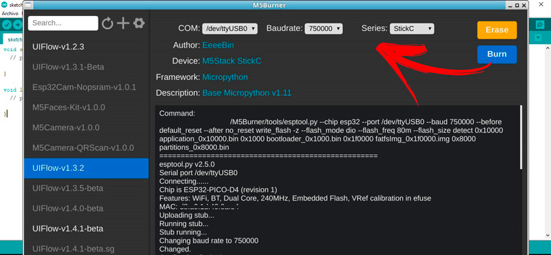
- Go to the left panel and choose the option UIFlow (in its latest version).
- Enter your Internet username and password. This will allow you to obtain the necessary settings for the WiFi network with which the board will work, making it appear on the screen a QR code with the API. If you do not want to do it through WiFi, you can do it through a USB port, with which we continue with the example.
- Configure the field COM (with the corresponding port) and baudrate (choose 750000).
- After this, you’re going to have to click on Burn.
- Next, you will find a screen with the development and information of the entire environment.
Look at this example:
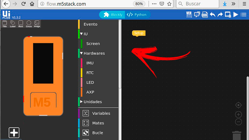
- Open the programming environment. You will find the screen divided in two, the left part shows the functions menu, while the other section is the programming development.
- In the left pane go to the top menu and choose Title.
- write a name and drag it with the mouse to the drawing of the device.
- Then select when a window opens write in the field Text whatever you need.
- When you have finished with these steps, go back to the menu and choose Label. A series of options will be displayed in the right sector, choose the first impression in it.
- The previous step so that the group of codes belonging to that label is automatically placed. Modify the menu in label0 and write what you want to appear. For example, IP@P.
- Then press Event and choose a button. Drag it to the programming sector and define what you are going to relate it to, with IMU, CRT, leds either AXP.
- For example, if you choose leds you’re going to have to select what you want the button to do. That is, if you want the led to turn off or on.
- When you are done with this part you can press save. You must take into account that for the blocks to work you need to join them to the commands, for this you must join them as close as possible until they become the same color.
Programming with Python
The advantage that Python offers is that it is not necessary to carry out the entire process.or that it is executed with the other languages, in this case the instructions must be entered and the program interprets them without any other step to do. For this reason, it is an ideal environment to learn to program Arduino. The current versions that exist of this language is python Y python 3being the latter the only one that receives support.
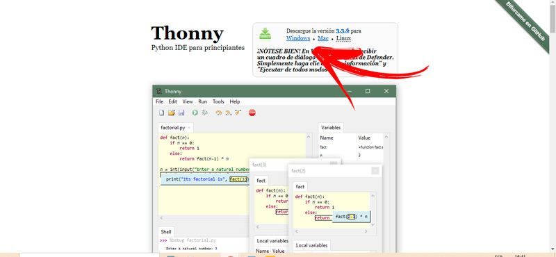
The program can be started from a Linux console via the super user command sudo apt-get install idle3. But if you don’t have Linux, since your computer has a Windows or MacOS operating system, you should use Tony Python IDE. For this you will have to visit https://thonny.org/ Y choose the button with the corresponding OS.
Once you have downloaded this software you should know these topics to program your Arduino:
- Variables and data: It is important that you know and the variables can have different values and be modified according to the program that executes them. Unlike other environments, in Python it is not necessary to define variables before using them.
- Lists: These elements are defined when the data is enclosed in square brackets, being numbered from 0 to length -1. It is important to take into account whether or not the extreme elements are included.
- Tuples: The difference with lists is that tuples contain the data enclosed in parentheses.
- Operators: There are a large number of operators that allow you to perform different actions. The most common ones are the arithmetic ones, the relational thread assignment ones.
Once you have defined these concepts, you must carry out the following process:
- if you want to write Arduino Course on the Internet Step by Stepyou will have to write in the terminal the command print(”Arduino Course on the Internet Step by Step”).
- You can then run the program by entering python3 one.py.
To practice do the example of programming a weather station with Arduino.
Once you have opened the program on your computer and know the port type the following:
~/Descargas/UIFlowIDE$ screen /dev/ttyUSB1 115200
Reboot the device by holding 6 seconds to pay and 2 seconds to boot, then enter the following:
I (9) boot: ESP-IDF v3.3-beta1-270-g6ffef3bc1 2nd stage bootloader

I (9) boot: compile time 09:26:17

I (9) boot: Enabling RNG early entropy source...

I (14) boot: SPI Speed : 80MHz

I (18) boot: SPI Mode : DIO

I (22) boot: SPI Flash Size : 4MB

I (26) boot: Partition Table:

I (29) boot: ## Label Usage          Type ST Offset   Length

I (37) boot: 0 nvs              WiFi data        01 02 00009000 00006000

I (44) boot: 1 phy_init         RF data          01 0

>>> I (9) boot: ESP-IDF v3.3-beta1-270-g6ffef3bc1 2nd stage bootloader

I (9) boot: compile time 09:26:17

I (9) boot: Enabling RNG early entropy source...

I (14) boot: SPI Speed : 80MHz

I (18) boot: SPI Mode : DIO

I (22) boot: SPI Flash Size : 4MB

I (26) boot: Partition Table:

I (29) boot: ## Label Usage          Type ST Offset   Length

I (37) boot: 0 nvs              WiFi data        01 02 00009000 00006000

I (44) boot: 1 phy_init         RF data          01 01 0000f000 00001000

I (52) boot: 2 factory          factory app      00 00 00010000 001e0000

I (59) boot: 3 internalfs       Unknown data     01 81 001f0000 00210000

I (52) boot: 2 factory          factory app      00 00 00010000 001e0000

I (59) boot: 3 internalfs       Unknown data     01 81 001f0000 00210000

I (67) boot: End of partition table

I (71) esp_image: segment 0: paddr=0x00010020 vaddr=0x3f400020 size=0xdad24 (896292) map

I (337) esp_image: segment 1: paddr=0x000ead4c vaddr=0x3ffb0000 size=0x02e9c ( 11932) load

I (341) esp_image: segment 2: paddr=0x000edbf0 vaddr=0x40080000 size=0x00400 ( 1024) load

I (344) esp_image: segment 3: paddr=0x000edff8 vaddr=0x40080400 size=0x02018 ( 8216) load

I (355) esp_image: segment 4: paddr=0x000f0018 vaddr=0x400d0018 size=0xd3a10 (866832) map

I (611) esp_image: segment 5: paddr=0x001c3a30 vaddr=0x40082418 size=0x116c0 ( 71360) load

I (634) esp_image: segment 6: paddr=0x001d50f8 vaddr=0x400c0000 size=0x00064 ( 100) load

I (635) esp_image: segment 7: paddr=0x001d5164 vaddr=0x50000000 size=0x00808 ( 2056) load

I (654) boot: Loaded app from partition at offset 0x10000

I (654) boot: Disabling RNG early entropy source...

I (655) cpu_start: Pro cpu up.

I (659) cpu_start: Application information:

I (664) cpu_start: Compile time: 09:26:24

I (669) cpu_start: Compile date: Jun 10 2019

I (674) cpu_start: ESP-IDF: 3-beta1-270-g6ffef3bc1

I (680) cpu_start: Starting app cpu, entry point is 0x400831f4

I (0) cpu_start: App cpu up.

I (691) heap_init: Initializing. RAM available for dynamic allocation:

I (698) heap_init: At 3FFAE6E0 len 00001920 (6 KiB): DRAM

I (704) heap_init: At 3FFB9970 len 00026690 (153 KiB): DRAM

I (710) heap_init: At 3FFE0440 len 00003AE0 (14 KiB): D/IRAM

I (716) heap_init: At 3FFE4350 len 0001BCB0 (111 KiB): D/IRAM

I (723) heap_init: At 40093AD8 len 0000C528 (49 KiB): IRAM

I (729) cpu_start: Pro cpu start user code

I (75) cpu_start: Starting scheduler on PRO CPU.

I (0) cpu_start: Starting scheduler on APP CPU.

Internal FS (FatFS): Mounted on partition 'internalfs' [size: 2162688; Flash address: 0x1F0000]

----------------

Filesystem size: 2101248 B

Used: 503808 B

Free: 1597440 B

----------------

I (388) [TFTSPI]: attached display device, speed=8000000

I (388) [TFTSPI]: bus uses native pins: false

[ M5 ] node id:1234567890ab, api key:12345678

I (4344) system_api: Base MAC address is not set, read default base MAC address from BLK0 of EFUSE

I (4344) system_api: Base MAC address is not set, read default base MAC address from BLK0 of EFUSE

I (4432) phy: phy_version: 4007, 1234567, Jan 11 2019, 16:45:07, 0, 0

I (4436) modsocket: Initializing

Connect Wi-Fi: SSID:Miwifi PASSWD:Mipass network...

..................

Network config: ('192.168.43.185', '255.255.255.0', '192.168.43.1', '192.168.43.1')

M5Cloud connected.

m5cloud thread begin .....
Next, press the Ctrl + C keys at the same time to interrupt the software, this will let you know:
Unhandled exception in thread started by <bound_method>

Traceback (most recent call last):

File "flowlib/lib/time_ex.py", line 56, in timeCb

KeyboardInterrupt:

Unhandled exception in thread started by <bound_method>

Traceback (most recent call last):

File "flowlib/m5cloud.py", line 187, in _daemonTask

File "flowlib/lib/time_ex.py", line 56, in timeCb

KeyboardInterrupt:

Traceback (most recent call last):

File "flow.py", line 43, in <module>

File "flowlib/m5cloud.py", line 224, in run

File "flowlib/m5cloud.py", line 199, in _backend

File "flowlib/m5cloud.py", line 187, in _daemonTask

File "flowlib/lib/time_ex.py", line 56, in timeCb

KeyboardInterrupt:
Finally, the MicroPython interface will be:
MicroPython v1.10-273-g4616ff72f-dirty on 2019-06-10; ESP32 module with ESP32

Type "help()" for more information.

>>>

Welcome to MicroPython on the ESP32!

For generic online docs please visit http://docs.micropython.org/

For access to the hardware use the 'machine' module:

import machine

pin12 = machine.Pin(12, machine.Pin.OUT)

value(1)

pin13 = machine.Pin(13, machine.Pin.IN, machine.Pin.PULL_UP)

print(pin13.value())

i2c = machine.I2C(scl=machine.Pin(21), sda=machine.Pin(22))

scan()

writeto(addr, b'1234')

readfrom(addr, 4)

Basic WiFi configuration:

import network

sta_if = network.WLAN(network.STA_IF); sta_if.active(True)

scan() # Scan for available access points

connect("<AP_name>", "<password>") # Connect to an AP

isconnected() # Check for successful connection

Control commands:

CTRL-A – on a blank line, enter raw REPL mode

CTRL-B – on a blank line, enter normal REPL mode

CTRL-C – interrupt a running program

CTRL-D – on a blank line, do a soft reset of the board

CTRL-E – on a blank line, enter paste mode

For further help on a specific object, type help(obj)

For a list of available modules, type help('modules')

>>>
Programming with scratch
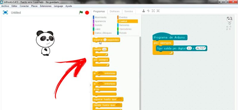
Scratch, as a programming environment, has the advantage of the simplicity it offers users to carry out robotics projects and electronics without having advanced knowledge in programming languages. To do this, you use blocks that are assembled according to the functions and characteristics that the user needs.
If you want to program an Arduino board with Scratch you will have to do this step by step:
- The first thing you will have to do is download the Scratch IDE. For this you will have to enter with your trusted browser to the page
https://mblock.makeblock.com/en-us/wait a few seconds for the platform to detect your computer’s operating system and then click on the button Discharge. - Once you have opened this program you will find the screen divided into three sectionsbeing the one in the middle where you will see all the functions and the one on the right the environment in which you will write the codes in block.
- Now you will have to connect the board with your computer.
- Enter the tool License plate and choose the model of your Arduino.
- Go to the menu extensions Choose Arduino and also Communication.
- Then go to the tab Connect and check in Serial port that the program has recognized the Arduino connection. You can detect this if you write the name of the port to which you connected the board.
- Once you’ve done these steps, in the middle column you’ll find the name of the board with a green button. Which means that all the connections are made correctly.
- Go to the menu in the middle of the screen and select the tab programs.
- A menu will be displayed in which you will have to choose robots (if you are doing a project of this nature, you can also choose others), to start with the programming, the option Arduino program.
- Then click on the tab Control.
- Choose the command block What do you want the robot to do?
- Go back to the Robots tool and click on the next action the board will perform.
- When you finish choose again Control and choose a new function. This is repetitive until you finish programming.
The best free online courses to learn to program Arduino from scratch that you should know
If you’re willing to advancing in the world of Arduino programming it is important that you know the best online courses for free. These platforms will help you learn from scratch all the variants offered by the electronic board.
Check out:
Arduino on the Internet Step by Step
We couldn’t start this list without recommending our own free course to learn Arduino programming. We have to offer you a large number of strategically separated topics so that learning is much faster and better, regardless of the user’s computing experience.
In order for you to enjoy the guides and tutorials on the different Arduino boards, the programming environment and the robotics projects for adults and children, you will need to go to Arduino IPAP Course and choose the theme that you like the most. Also, you can ask us any kind of query in the section of Comments.
Arduino Project Hub
It is the official page of Arduino where you can find a wide variety of projects, ideas to build electronic devices with plates, materials and programming codes. these projects they are uploaded by the users themselves, so the community forms a strategic part of this website. You will have to visit with your browser https://create.arduino.cc/projecthub to know the different ideas that can be used according to your computer skills.
Ikkaro.com
It is a platform dedicated to home experiments, not only robotics but also a wide variety of topics. Because of this the Arduino board forms an important part of the project. If you want to know more and download the tutorials you will have to enter the page and explore its content.
Computing