
Index:
UPDATED ✅ Do you want to know more about Arduino sketch structures and how to make one? ⭐ ENTER HERE ⭐ and Learn Everything FROM ZERO!
The Sketch is one of the most important elements in the IDE programming environment.. Due to this it is necessary, if you want to become a true expert, that you know what the structure of the sketches is.
This information can be found in the following paragraphs. We will explain, in detail, what a Sketch is and what these programs are for. Also, you we will show all the parts of an Arduino code.
We invite you to continue reading until the end because you will find information about Sketch examples you can use to learn programming. Check out.
What is an Arduino Sketch and what are these programs for?
If you are going to create a project with an Arduino board you will not only need to use the pins to connect the different elements between the board, circuits and hardware you want. You will also have to program the Arduino model that you have so that it emits electronic signals and the project can be carried out. For example, if you create a robot in the first stage you will have to make the necessary connections correctly, but this will not help you because the robot will remain immobile.
So that you will have to program their movements for the project to make sense. In order for the robot to move, following the example, you must configure the Arduino board in the IDE environment. This is a software that uses a special language and divides each of the projects into a Sketch or sketch. Therefore, a Sketch in Arduino is a program in which all the codes are saved that are used to make the board perform certain tasks.
When you find a file with the extension .ino it means that it is a Sketch. For it to work correctly, you must bear in mind that the name of the folder in which it is save the sketch must be included in a directory with the same name as the Sketch.
You can save a program Arduino in different files, but these folders must always be in the same directory as the main file. Finally, you have to keep in mind that a Sketch is made up of 2 instructions, one called loop() and the other setup(). The first being in charge of executing the program instructions cyclically, or by loop, while the second is the statement used to carry out the configuration.
Structure of a Sketch What are all the parts of the Arduino code?
As we mentioned before setup() and loop() are part of a Sketchbut these are not the only components that you can find in a program of Arduino.
We will show you below what are all the parts of the code of an electronic board that you can use in the IDE:
Structure
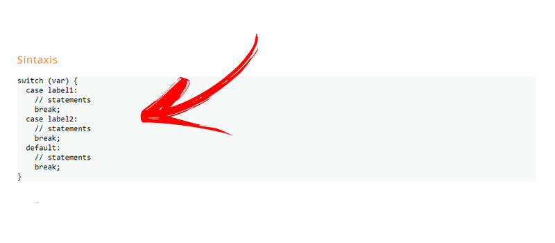
Analyzing a little deeper the structure of the Sketchwe can say that the setup() is used to start a sketchinitializing libraries, variables, and how the board’s pins will be used, among other things. It is used every time the Arduino is powered on or reset. Therefore, it must be written only once and at the beginning of the code.
An example of this is:
int buttonPin = 5;

void setup() {

begin(9600);

pinMode(buttonPin, INPUT);

}

void loop() {

// ...

}
The other component that integrates the Sketch is the loop(). This statement or instruction is used after creating the setup() for indicate the initial values that a certain function will have. This way you can control the board much easier every time you use these loops.
Its use is as follows:
int buttonPin = 5;

// setup initializes serial and the button pin

void setup() {

begin(9600);

pinMode(buttonPin, INPUT);

}

// para controlar el pin 5,

// además, si Se presiona enviará Serial

void loop() {

if (digitalRead(buttonPin) == HIGH) {

write('H');

}

else {

write('L');

}

delay(1000);

}
You can see from the examples above that other comparators are usedso the structure of a Sketch it can also be subdivided into more variables.
Within these components you can find:
- Of control: used to establish conditions or execute a given procedure. In this group are break; continue; do… while; for; goto; if; if…else; return; switch case Y while.
- Arithmetic: You should use these functions when you need to program a primary math operation in the environment. Arduino. These buyers are =; +; –; /; * Y %.
- From syntax: they help to enter single or multi-line comments, as well as to name a constant value or include it in a program build. are used in this case #define; #include; {}; semicolon (;); // for one line comments next to the code and /* */ to open and close a multi-line comment.
- Booleans: when you need to enter a logical variable you have to use these operators in the IDE. Within them are || (or); && (and) and ! (not).
- For comparison: This subcategory is one of the most used in programming, as its name indicates, it is used to compare a condition and return a result to continue with the procedure. In this group is used = = (equal to); > (greater than); >= (greater than or equal to); (smaller than); (less than or equal to) and != (not equal to).
- Compounds: these operators are used within a Sketch structure when a combination of other components is needed. That is, they fulfill a double function. Because of this you can use &= (and bitwise composite); — (decrease); /= (division with compound method); ++ (increase); %= (composite module); *= (compound multiplication); |= (or bitwise composite); -=(compound subtraction) and += (composite sum).
- Bitwise: bitwise operators work with binary numbers in which a relation must be established according to a certain rule. operators are used >> (go to the right); (Go to the left); ~ (not bitwise); | (or bitwise); ^ (bitwise xor) and & (and bitwise).
- Pointer access: * Y & are the operators you can use in this group.
Values
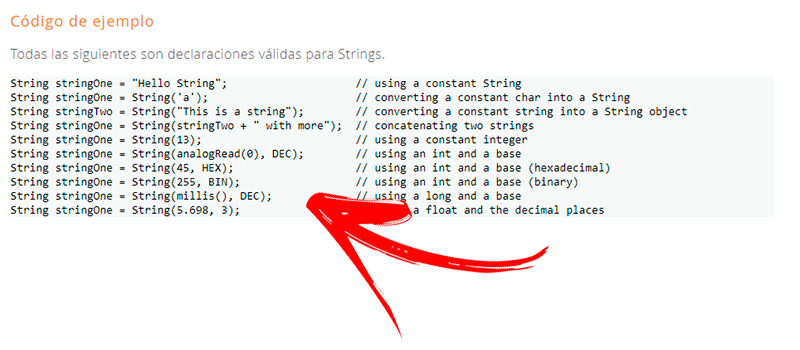
In this section constants, qualifiers, scope and data types are found which are used in programming an Arduino board.
Variables can be divided into:
- Constants: are used to make it easier to read the nameplate language. You can find the values that a pin can take and the input or output configuration mode. The most used are false; floating point constants; HIGH; LOW; INPUT; INPUT_PULLUP; integer constants; LED_BUILTIN; OUTPUT Y true.
- Data classes: when you need to indicate in the programming language what type of data you are working with, you must use this group. Therefore, they can be grouped in this category array; boolean; byte; char; double; float; int; long; shorts; string (as a character array); string (Object); unsigned char; unsigned int; unsigned length; void Y word.
- of uses: this category of variables is used by the program to return a given number of bytes from an array. So you can enter it in the IDE PROGEM Y size of.
- Of conversation: the variables found in this group convert a value to a certain data type. They find each other byte; char; float; int; long Y word.
- Scope qualifiers: these variables are used to modify the behavior of the variable itself. This indicates that it is read-only or a global variable, among other functions. The most commons are build; static; variable scope Y volatile.
Functions
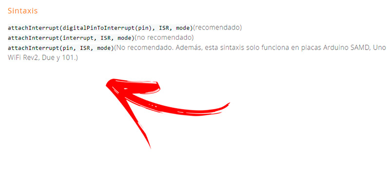
In the language used in the Arduino codethe functions part is the one intended to tell the program what type of action a variable should perform.
They can be divided:
- Input and output: You work with these components when you need to establish a destination for the current or wave received by the board. Are used noTone; pulseIn; pulseInLong; shiftIn; shiftOut Y tone.
- Of time: in a code it is possible to use these components to indicate an action that is related to time, for example, the milliseconds that the silver must wait before delivering an action. used for these components delayed; delayMicroseconds; mics Y millis.
- Digital: It is used to configure the inputs and outputs of the digital pins that a board has. Therefore, it is possible to find the functions digitalRead; digitalWrite Y pinMode.
- Analog: As with the previous functions, these actions are dedicated to configuring analog pins that an Arduino board has. Because of this you can find analogRead; analogWrite Y analogReference (PWM). But when you use a model Arduino DUE or Arduino ZERO you will have to enter the functions analogReadResolution Y analogWriteResolution to work.
- Math: these functions allow you to perform mathematical calculations within the program code. The most used are abs; constrain; map; max; min; wow Y sqrt.
- Interruptions: These functions are used to activate or deactivate a certain process. Within this group are interrupt Y noInterrupts. On the other hand, if an external interrupt is needed, the ones used are attachInterrupt Y detachInterrupt.
- bits and bytes: these programming tools are used to indicate that bits or bytes within a variable should be extracted. Therefore, the functions usually used are bit; bitClear; bitRead; bitSet; bitWrite; highByte Y lowByte.
- Communication: This group is one of the most used in IDE programming, since it allows the Arduino board to communicate with a computer or with any other hardware. The functions you can find are Serial Y streaming.
- Random numbers: these functions allow you to generate numbers to create a sequence that will always be the same. Those in this group are randomSeed Y random. But when you work with models DUE Y ZERO in 32u4 and you need to connect mouse and keyboard, the functions you will use are Keyboard Y mouse.
Learn step by step how to program a simple Sketch for your Arduino project
In this section we will put into practice everything that was shown in the previous paragraphsso you should pay attention and, if for any reason you made a mistake, we recommend you restart the steps so as not to drag the error.
The process that you will have to do in the programming of a simple Arduino project are the following:
Comments
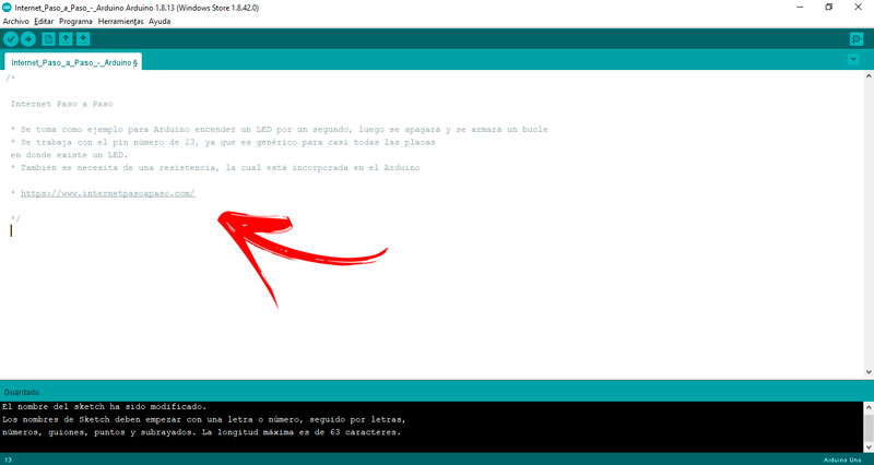
The comments are all the annotations that are made in the code to introduce the operation of the program, to be the author or why one function is used instead of another. There are two types of comments, multiline (found between the symbols /* Y */) and the single line (which are represented by using //). You should keep in mind that comments are not part of the program and therefore is ignored by the Arduino.
An example of this is:
/*

Internet Paso a Paso

Se toma como ejemplo para Arduino encender un LED por un segundo, luego se apagará y se armará un bucle

Se trabaja con el pin número de 13, ya que es genérico para casi todas las placas

en donde existe un LED.

También se necesita de una resistencia, la cual está incorporada en el Arduino

*/
variables
The variables are made up of a type, a name and a value. These are used so that each time the code name is written, the value of the variable can be retrieved.
For example, if within the program that is being created to turn on and off an LED connected to pin 13 of the board, you have to write:
int ledPin = 13;
This means that the variable name has been created ledPin to change (if you want in the future) the value, the type is int and its value is 13.
Functions
You must not forget that functions are actions that are introduced so that one variable perform a certain procedure.
This is how it should be entered into the software being programmed:
void setup()

{

pinMode(ledPin, OUTPUT); // para indicar una salida en un pin digital

}
The line setup() shows the data of the function type, the return type that the code will have are void Y ()while the body of the function is { pinMode(ledPin, OUTPUT); // to indicate an output on a digital pin }. Inside that body is pinMode . This function indicates that the parameters ledPin Y OUTPUT must go through a digital pin as output (this is why it is clarified in the comment // to indicate an output on a digital pin).
pinMode(), digitalWrite() and delay()
These functions provide specific prompts to the command, so you’ll need to know each one:
- pinMode(): it is used to establish if a pin of the Arduino board will work as input or output of the circuit. If it is an input then the connector will detect a sensor, while if it is a output will be an actuator (in the example we are developing it will be the led).
- digitalWrite(): in this function you can set the value of a pin. It is directly related to HIGH Y LOW, since these indicators will configure the type of voltage. An example of this would be to place the pinMode function in 5V, for this it will be necessary to enter digitalWrite(ledPin, HIGH);. If you need it to work at 0 volts, you have to write digitalWrite(ledPin, LOW);.
- delay(): this function is responsible for delaying the process before continuing to the next line of code. It is expressed in milliseconds, so the value 1000 represents 1 second. Its use is delay(1000);.
Setup() and Loop()
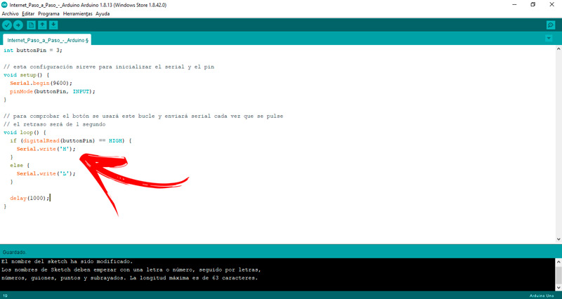
We have already discussed that setup() it is the function in charge of configuring options within a code, but this tool is not the only one that should be used frequently in the programming of a board Arduino. is also loop(), which will allow permanent control of the plaque. With this function you will be able to know if you are on the right track and the functions you add are working according to what you need.
An example of how setup() and loop() are used is:
int buttonPin = 3;

// esta configuración sireve para inicializar el serial y el pin

void setup() {

begin(9600);

pinMode(buttonPin, INPUT);

}

// para comprobar el botón se usará este bucle y enviará serial cada vez que se pulse

// el retraso será de 1 segundo

void loop() {

if (digitalRead(buttonPin) == HIGH) {

write('H');

}

else {

write('L');

}

delay(1000);

}
Arduino Sketch examples for you to learn to program your own
What you will see next it will help you practice yourself different Projects.
Pay attention to the details and repeat them over and over so you understand the whole process:
Blink Sketch
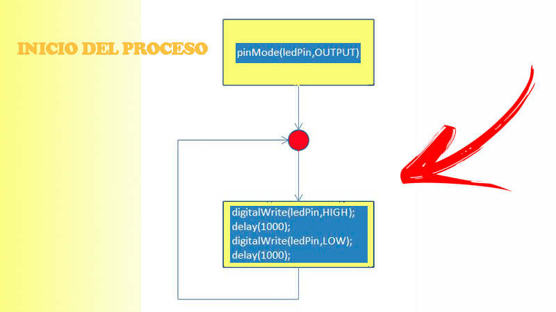
This project will help you to blink an integrated led on the Arduino board., which has most of the plate models. in version ONE, And a and Zero, the pin used is number 13, while in the MKR1000 (for example) it is digital 6.
The code you will use is:
void setup() {

pinMode(ledPin, OUTPUT);

}

{

digitalWrite(ledPin, HIGH);

delay(1000);

digitalWrite(ledPin, LOW);

delay(1000);

}
Obstacle dodging robot
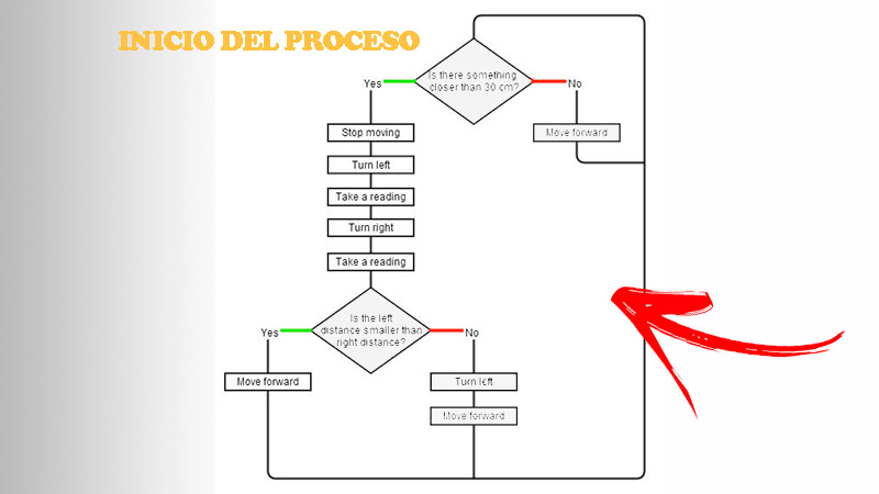
In this project we will show you the flow of processes that you must take into account when programmingcorrectly, a device that avoids obstacles. The diagram which we show you in the following figure It will help you better understand the process.
While the project code will be something like this:
#include <AFMotor.h>

#include <NewPing.h>

#include <Servo.h>

#define TRIG_PIN A4

#define ECHO_PIN A5

#define MAX_DISTANCE 200

#define MAX_SPEED 190

#define MAX_SPEED_OFFSET 20

NewPing sonar(TRIG_PIN, ECHO_PIN, MAX_DISTANCE);

AF_DCMotor motor1(1, MOTOR12_1KHZ);

AF_DCMotor motor2(3, MOTOR12_1KHZ);

Servo myservo;

boolean goesForward=false;

int distance = 100;

int speedSet = 0;

void setup() {

attach(9);

write(115);

delay(2000);

distance = readPing();

delay(100);

distance = readPing();

delay(100);

distance = readPing();

delay(100);

distance = readPing();

delay(100);

}

void loop() {

int distanceR = 0;

int distanceL = 0;

delay(40);

if(distance<=15)

{

moveStop();

delay(100);

moveBackward();

delay(300);

moveStop();

delay(200);

distanceR = lookRight();

delay(200);

distanceL = lookLeft();

delay(200);

if(distanceR>=distanceL)

{

turnRight();

moveStop();

}else

{

turnLeft();

moveStop();

}

}else

{

moveForward();

}

distance = readPing();

}

int lookRight()

{

write(50);

delay(500);

int distance = readPing();

delay(100);

write(115);

return distance;

}

int lookLeft()

{

write(170);

delay(500);

int distance = readPing();

delay(100);

write(115);

return distance;

delay(100);

}

int readPing() {

delay(70);

int cm = sonar.ping_cm();

if(cm==0)

{

cm = 250;

}

return cm;

}

oid moveStop() {

run(RELEASE);

run(RELEASE);

}

void moveForward() {

if(!goesForward)

{

goesForward=true;

run(FORWARD);

run(FORWARD);

for (speedSet = 0; speedSet < MAX_SPEED; speedSet +=2)

{

setSpeed(speedSet);

setSpeed(speedSet+MAX_SPEED_OFFSET);

delay(5);

}

}

}

void moveBackward() {

goesForward=false;

run(BACKWARD);

run(BACKWARD);

for (speedSet = 0; speedSet < MAX_SPEED; speedSet +=2)

{

setSpeed(speedSet);

setSpeed(speedSet+MAX_SPEED_OFFSET);

delay(5);

}

}

void turnRight() {

run(FORWARD);

run(BACKWARD);

delay(300);

run(FORWARD);

run(FORWARD);

}

void turnLeft() {

run(BACKWARD);

run(FORWARD);

delay(300);

run(FORWARD);

run(FORWARD);

}
Access control system by reading RFID cards
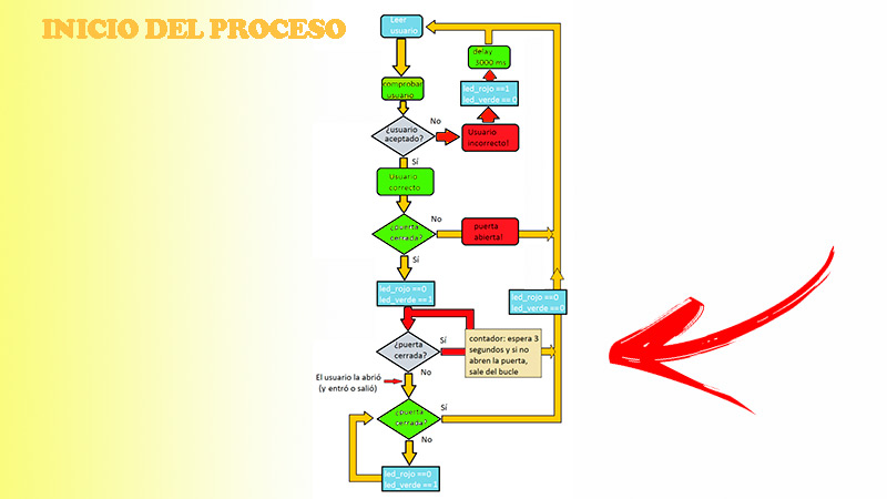
First it is important to define what an RFID card is It is a device that works with radio frequency and is used to send information that serves to identify or transmit a specific data of an object. Due to this, it can be used in a practical way. an Arduino board to create a reader that allows controlling the access of people.
After having practiced the two previous projectsyou will be able to program this Sketch a bit more complex. Because of this we will show you first the flowchart of the operations so you can carry out your task without errors. What you should do now is write these codeswhich are not definitive, that will help you compare what you entered in the Arduino IDE environment.
For this you will have to write:
#include <SPI.h>

#include <MFRC522.h>

#define RST_PIN 9

#define SS_PIN 10

MFRC522 mfrc522(SS_PIN, RST_PIN);

void setup() {

begin(9600);

while (!Serial);

begin();

PCD_Init();

delay(4);

PCD_DumpVersionToSerial();

println(F("Scan PICC to see UID, SAK, type, and data blocks..."));

}

void loop() {

if ( ! mfrc522.PICC_IsNewCardPresent()) {

return;

}

if ( ! mfrc522.PICC_ReadCardSerial()) {

return;

}

PICC_DumpToSerial(&(mfrc522.uid));

}
What you have to do now is change the key of a sector using Key-A: A0 A1 A2 A3 A4 Y Key-B: B0 B1 B2 B3 B4.
You must write:
#include <SPI.h>

#include <MFRC522.h>

#define RST_PIN 9

#define SS_PIN 10

MFRC522 mfrc522(SS_PIN, RST_PIN);

MFRC522::MIFARE_Key keyA = {keyByte: {0xFF, 0xFF, 0xFF, 0xFF, 0xFF, 0xFF}};

MFRC522::MIFARE_Key keyB = {keyByte: {0xFF, 0xFF, 0xFF, 0xFF, 0xFF, 0xFF}};

// Nuevas claves para el cifrado

MFRC522::MIFARE_Key nuevaKeyA = {keyByte: {0xA0, 0xA1, 0xA2, 0xA3, 0xA4, 0xA5}};

MFRC522::MIFARE_Key nuevaKeyB = {keyByte: {0xB0, 0xB1, 0xB2, 0xB3, 0xB4, 0xB5}};

// Datos del sector al cual pertenece el usuario aceptado

byte sector = 15;

void mostrarByteArray(byte* buffer, byte bufferSize) {

for (byte i = 0; i < bufferSize; i++) {

print(buffer[i] < 0x10 ? " 0" : " ");

print(buffer[i], HEX);

}

}

void setup() {

begin(9600);

while (!Serial);

begin();

PCD_Init();

println(F("Acerque la tarjeta al lecto."));

println(F("Las claves de esta tarjeta deben ser:"));

print("Key-A: ");

mostrarByteArray(keyA.keyByte, MFRC522::MF_KEY_SIZE);

println();

print("Key-B: ");

mostrarByteArray(keyB.keyByte, MFRC522::MF_KEY_SIZE);

println();

println(F("MUY IMPORTANTE: durante el proceso de actualización de las claves "));

println(F("no separes la tarjeta del lector hasta que no termine."));

}

void loop() {

// Si no hay una tarjeta para usar el programa no avanza

if (!mfrc522.PICC_IsNewCardPresent()) {

return;

}

if (!mfrc522.PICC_ReadCardSerial()) {

return;

}
After this you will have to program for the information to appear on the serial monitor:
print(F("UID de la tarjeta:"));

mostrarByteArray(mfrc522.uid.uidByte, mfrc522.uid.size);

println();

print(F("Tipo de tarjeta: "));

MFRC522::PICC_Type piccType = mfrc522.PICC_GetType(mfrc522.uid.sak);

println(mfrc522.PICC_GetTypeName(piccType));

boolean resultado = cambiarKeys(&keyA, &keyB, &nuevaKeyA, &nuevaKeyB, sector);

if (resultado) {

print(F("Claves del sector "));

println(sector);

print(F("Key-A: "));

mostrarByteArray(nuevaKeyA.keyByte, MFRC522::MF_KEY_SIZE);

println();

print(F("Key-B: "));

mostrarByteArray(nuevaKeyB.keyByte, MFRC522::MF_KEY_SIZE);

println();

} else {

print(F("Claves del sector "));

println(sector);

print(F("Key-A: "));

mostrarByteArray(keyA.keyByte, MFRC522::MF_KEY_SIZE);

println();

print(F("Key-B: "));

mostrarByteArray(keyB.keyByte, MFRC522::MF_KEY_SIZE);

println();

}

// Autenticar utilizando la clave Key-A

estado = (MFRC522::StatusCode)mfrc522.PCD_Authenticate(MFRC522::PICC_CMD_MF_AUTH_KEY_A, bloqueTrailer, antiguaKeyA, &(mfrc522.uid));

// Si no consigue autenticar que no continúe

if (estado != MFRC522::STATUS_OK) {

print(F("Fallo en la autenticación Key-A: "));

println(mfrc522.GetStatusCodeName(estado));

return false;

}

// Mostrar el sector completo del usuario

println(F("Informción en el sector:"));

PICC_DumpMifareClassicSectorToSerial(&(mfrc522.uid), antiguaKeyA, sector);

println();

// Leyendo datos del bloque

print(F("Leyendo datos del bloque ")); Serial.print(bloqueTrailer);

println(F(" ..."));

estado = (MFRC522::StatusCode) mfrc522.MIFARE_Read(bloqueTrailer, buffer, &size);

if (estado != MFRC522::STATUS_OK) {

print(F("Fallo al leer el bloque: "));

println(mfrc522.GetStatusCodeName(estado));

return false;

}

print(F("Información en el bloque ")); Serial.print(bloqueTrailer); Serial.println(F(":"));

mostrarByteArray(buffer, 16); Serial.println();

println();

// Autenticar utilizando la clave Key-B

estado = (MFRC522::StatusCode)mfrc522.PCD_Authenticate(MFRC522::PICC_CMD_MF_AUTH_KEY_B, bloqueTrailer, antiguaKeyB, &(mfrc522.uid));

// Si no consigue autenticar que no continúe

if (estado != MFRC522::STATUS_OK) {

print(F("Fallo en la uatenticación Key-B: "));

println(mfrc522.GetStatusCodeName(estado));

return false;

}

if (nuevaKeyA != nullptr || nuevaKeyB != nullptr) {

// Para recoorer todos los bytes que tiene la clave elegida.

for (byte i = 0; i < MFRC522::MF_KEY_SIZE; i++) {

if (nuevaKeyA != nullptr) {

buffer[i] = nuevaKeyA->keyByte[i];

}

if (nuevaKeyB != nullptr) {

buffer[i + 10] = nuevaKeyB->keyByte[i];

}

}

}

return true;

}
Computing